
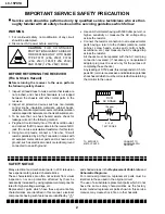
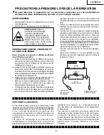
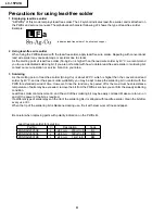
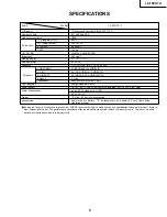


LC-15PX1U
6
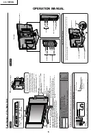
OPERATION MANUAL
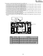
Speaker
HEADPHONE jac
k
Plug the headphone mini-plug into the Headphone
jac
k
located on the front of the main unit.
CARD lamp
The CARD lamp lights up depending on the
usage status of the card.
F
or details
, see
Status
of the CARD lamp
belo
w
.
PC car
d slot
×
2
OPC (Optical Picture Contr
ol) indicator
The OPC indicator lights up g
reen when the
“OPC”
is
set to
“ON”.
Remote sensor
OPC (Optical Picture Contr
ol) sensor
Speaker
MIC
Microphone used f
or the A
udio Message Board
function.
PO
WER/W
AKE UP
TIMER indicator
PO
WER indicator lights up g
reen when the po
w
e
r is on, and red
when in the standb
y mode (the indicator will not light when the main
po
w
e
r is off), and or
ange when the
W
a
ke
Alar
m is set (the indicator
will light when in the standb
y mode).
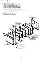
Part Names of the Main Unit
Controls
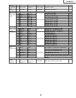
Status of the CARD lamp
•
TV/VIDEO
,
CH (
)/(
),
VOL (–)/(+)
and
MENU
on the main unit have the same functions as the same buttons on the remote control.
Fundamentally, this operation manual provides a description based on operation using the remote control.
To change the vertical angle of the LCD TV
set, tilt the screen up to 5 degrees forward or
10 degrees backward. The display can also
be rotated up to 25 degrees to right and left.
When tilting or rotating the display, be sure
to securely hold down the stand.
Please adjust the angle so that the display
can be watched most comfortably.
MAIN POWER
Upper control panel
TV/VIDEO
MENU
CH (Channel)
(
)/(
)
VOL (Volume)
(–)/(+)
Tilt the displa
y
b
y
g
rab
bing onto the
carr
y
ing handle while securely holding
do
wn the stand with y
our hand.
Ho
w to adjust the angle
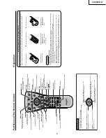
Listening with Headphones
Plug the headphone mini-plug into the HEADPHONE jack located on the front of the main unit.
On-screen display
20
VOL
UM
E
Adjust the sound volume
using
VOL (
+
)/
(
–
) on the
remote control.
Headphones
•
Headphones are not included in the supplied accessories.
•
No sound is heard from the main unit speakers when a headphone mini-plug is connected into the HEADPHONE jack.
Status of the LCD TV set
Lamp
On or on standby
When a card is not inserted in the PC card slot
Off
On
When the card in the PC card slot is accessed
Red
When the card in the PC card slot is not accessed
Green
On standby
When timer-recording is set
Orange
When there are audio messages that have yet to be listened
Blinking red
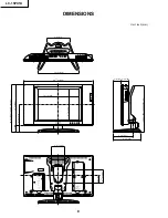
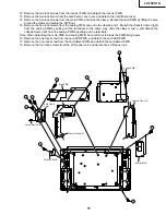
Terminals
Carr
ying handle
Rear Vie
w
Y
P
B
P
R
A
UDIO (L)
A
UDIO (R)
VIDEO
A
UDIO (R)
A
UDIO (L)
A
V
-IN2/OUT
ANT
. (Antenna terminal)
PO
WER INPUT
(DC 12V)
VIDEO
A
UDIO (L)
A
UDIO (R)
S-VIDEO
AV-
IN
1
COMPONENT
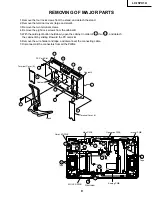
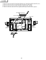
How to Fix the Cables
•
Pull the cables connected to each terminal through the holes and close the left and right terminal covers.
Push the cables into the grooves of the support covers. Insert the cable holder (supplied) from above the
support cover and fix the cables.
Cab
le holder
T
erminal co
ver
Suppor
t co
ver
T
erminal co
ver
Summary of Contents for LC-15PX1U
Page 27: ...LC 15PX1U 27 17 16 19 18 15 14 13 12 11 10 INVERTER Unit OPERATION Unit ANALOG Unit ...
Page 30: ...LC 15PX1U 8 7 10 9 6 5 4 3 2 1 A B C D E F G H 30 OVERALL WIRING DIAGRAM ...
Page 31: ...LC 15PX1U 31 17 16 19 18 15 14 13 12 11 10 ...
Page 33: ...33 6 5 4 3 2 1 A B C D E F G H LC 15PX1U SCHEMATIC DIAGRAM Ë OPERATION Unit ...
Page 34: ...LC 15PX1U 8 7 10 9 6 5 4 3 2 1 A B C D E F G H 34 ËMAIN Unit 1 14 ...
Page 35: ...LC 15PX1U 35 17 16 19 18 15 14 13 12 11 10 ...
Page 36: ...LC 15PX1U 8 7 10 9 6 5 4 3 2 1 A B C D E F G H 36 ËMAIN Unit 2 14 ...
Page 37: ...LC 15PX1U 37 17 16 19 18 15 14 13 12 11 10 ...
Page 38: ...LC 15PX1U 8 7 10 9 6 5 4 3 2 1 A B C D E F G H 38 ËMAIN Unit 3 14 ...
Page 39: ...LC 15PX1U 39 17 16 19 18 15 14 13 12 11 10 ...
Page 40: ...LC 15PX1U 8 7 10 9 6 5 4 3 2 1 A B C D E F G H 40 ËMAIN Unit 4 14 ...
Page 41: ...LC 15PX1U 41 17 16 19 18 15 14 13 12 11 10 ...
Page 42: ...LC 15PX1U 8 7 10 9 6 5 4 3 2 1 A B C D E F G H 42 ËMAIN Unit 5 14 ...
Page 43: ...LC 15PX1U 43 17 16 19 18 15 14 13 12 11 10 ...
Page 44: ...LC 15PX1U 8 7 10 9 6 5 4 3 2 1 A B C D E F G H 44 ËMAIN Unit 6 14 ...
Page 45: ...LC 15PX1U 45 17 16 19 18 15 14 13 12 11 10 ...
Page 46: ...LC 15PX1U 8 7 10 9 6 5 4 3 2 1 A B C D E F G H 46 ËMAIN Unit 7 14 ...
Page 47: ...LC 15PX1U 47 17 16 19 18 15 14 13 12 11 10 ...
Page 48: ...LC 15PX1U 8 7 10 9 6 5 4 3 2 1 A B C D E F G H 48 ËMAIN Unit 8 14 ...
Page 49: ...LC 15PX1U 49 17 16 19 18 15 14 13 12 11 10 ...
Page 50: ...LC 15PX1U 8 7 10 9 6 5 4 3 2 1 A B C D E F G H 50 ËMAIN Unit 9 14 ...
Page 51: ...LC 15PX1U 51 17 16 19 18 15 14 13 12 11 10 ...
Page 52: ...LC 15PX1U 8 7 10 9 6 5 4 3 2 1 A B C D E F G H 52 ËMAIN Unit 10 14 ...
Page 53: ...LC 15PX1U 53 17 16 19 18 15 14 13 12 11 10 ...
Page 54: ...LC 15PX1U 8 7 10 9 6 5 4 3 2 1 A B C D E F G H 54 ËMAIN Unit 11 14 ...
Page 55: ...LC 15PX1U 55 17 16 19 18 15 14 13 12 11 10 ...
Page 56: ...LC 15PX1U 8 7 10 9 6 5 4 3 2 1 A B C D E F G H 56 ËMAIN Unit 12 14 ...
Page 57: ...LC 15PX1U 57 17 16 19 18 15 14 13 12 11 10 ...
Page 58: ...LC 15PX1U 8 7 10 9 6 5 4 3 2 1 A B C D E F G H 58 ËMAIN Unit 13 14 ...
Page 59: ...LC 15PX1U 59 17 16 19 18 15 14 13 12 11 10 ...
Page 60: ...LC 15PX1U 8 7 10 9 6 5 4 3 2 1 A B C D E F G H 60 ËMAIN Unit 14 14 ...
Page 61: ...LC 15PX1U 61 17 16 19 18 15 14 13 12 11 10 ...
Page 62: ...LC 15PX1U 8 7 10 9 6 5 4 3 2 1 A B C D E F G H 62 ËANALOG Unit 1 4 ...
Page 63: ...LC 15PX1U 63 17 16 19 18 15 14 13 12 11 10 ...
Page 64: ...LC 15PX1U 8 7 10 9 6 5 4 3 2 1 A B C D E F G H 64 ËANALOG Unit 2 4 ...
Page 65: ...LC 15PX1U 65 17 16 19 18 15 14 13 12 11 10 ...
Page 66: ...LC 15PX1U 8 7 10 9 6 5 4 3 2 1 A B C D E F G H 66 ËANALOG Unit 3 4 ...
Page 67: ...LC 15PX1U 67 17 16 19 18 15 14 13 12 11 10 ...
Page 68: ...LC 15PX1U 8 7 10 9 6 5 4 3 2 1 A B C D E F G H 68 ËANALOG Unit 4 4 ...
Page 69: ...LC 15PX1U 69 17 16 19 18 15 14 13 12 11 10 ...
Page 70: ...70 6 5 4 3 2 1 A B C D E F G H LC 15PX1U ËR C LED Unit ...
Page 71: ...71 6 5 4 3 2 1 A B C D E F G H LC 15PX1U ËCARD LED Unit ...
Page 72: ...72 6 5 4 3 2 1 A B C D E F G H LC 15PX1U ËCARD DETECT Unit ...
Page 73: ...73 6 5 4 3 2 1 A B C D E F G H LC 15PX1U ËINVERTER Unit ...
Page 78: ...LC 15PX1U 8 7 10 9 6 5 4 3 2 1 A B C D E F G H 78 ANALOG Unit Side A ...
Page 79: ...LC 15PX1U 79 17 16 19 18 15 14 13 12 11 10 ...
Page 82: ...82 6 5 4 3 2 1 A B C D E F G H LC 15PX1U INVERTER Unit Side A ...


