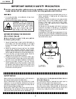
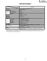
LC-15PX1U
4
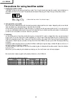
Precautions for using lead-free solder
1 Employing lead-free solder
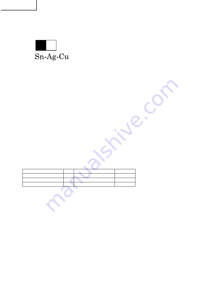
"All PWBs" of this model employs lead-free solder. The LF symbol indicates lead-free solder, and is attached on
the PWBs and service manuals. The alphabetical character following LF shows the type of lead-free solder.
Example:
2 Using lead-free wire solder
When fixing the PWB soldered with the lead-free solder, apply lead-free wire solder. Repairing with conventional
lead wire solder may cause damage or accident due to cracks.
As the melting point of lead-free solder (Sn-Ag-Cu) is higher than the lead wire solder by 40°C, we recommend
you to use a dedicated soldering bit, if you are not familiar with how to obtain lead-free wire solder or soldering bit,
contact our service station or service branch in your area.
3 Soldering
As the melting point of lead-free solder (Sn-Ag-Cu) is about 220°C which is higher than the conventional lead
solder by 40°C, and as it has poor solder wettability, you may be apt to keep the soldering bit in contact with the
PWB for extended period of time. However, Since the land may be peeled off or the maximum heat-resistance
temperature of parts may be exceeded, remove the bit from the PWB as soon as you confirm the steady soldering
condition.
Lead-free solder contains more tin, and the end of the soldering bit may be easily corroded. Make sure to turn on
and off the power of the bit as required.
If a different type of solder stays on the tip of the soldering bit, it is alloyed with lead-free solder. Clean the bit after
every use of it.
When the tip of the soldering bit is blackened during use, file it with steel wool or fine sandpaper.
Be careful when replacing parts with polarity indication on the PWB silk.
Indicates lead-free solder of tin, silver and copper.
Lead-free wire solder for servicing
Part No,
★
Description
Code
ZHNDAi123250E
J
φ
0.3mm
250g(1roll)
BL
ZHNDAi126500E
J
φ
0.6mm
500g(1roll)
BK
ZHNDAi12801KE
J
φ
1.0mm
1kg(1roll)
BM
L
F a
Summary of Contents for LC-15PX1U
Page 27: ...LC 15PX1U 27 17 16 19 18 15 14 13 12 11 10 INVERTER Unit OPERATION Unit ANALOG Unit ...
Page 30: ...LC 15PX1U 8 7 10 9 6 5 4 3 2 1 A B C D E F G H 30 OVERALL WIRING DIAGRAM ...
Page 31: ...LC 15PX1U 31 17 16 19 18 15 14 13 12 11 10 ...
Page 33: ...33 6 5 4 3 2 1 A B C D E F G H LC 15PX1U SCHEMATIC DIAGRAM Ë OPERATION Unit ...
Page 34: ...LC 15PX1U 8 7 10 9 6 5 4 3 2 1 A B C D E F G H 34 ËMAIN Unit 1 14 ...
Page 35: ...LC 15PX1U 35 17 16 19 18 15 14 13 12 11 10 ...
Page 36: ...LC 15PX1U 8 7 10 9 6 5 4 3 2 1 A B C D E F G H 36 ËMAIN Unit 2 14 ...
Page 37: ...LC 15PX1U 37 17 16 19 18 15 14 13 12 11 10 ...
Page 38: ...LC 15PX1U 8 7 10 9 6 5 4 3 2 1 A B C D E F G H 38 ËMAIN Unit 3 14 ...
Page 39: ...LC 15PX1U 39 17 16 19 18 15 14 13 12 11 10 ...
Page 40: ...LC 15PX1U 8 7 10 9 6 5 4 3 2 1 A B C D E F G H 40 ËMAIN Unit 4 14 ...
Page 41: ...LC 15PX1U 41 17 16 19 18 15 14 13 12 11 10 ...
Page 42: ...LC 15PX1U 8 7 10 9 6 5 4 3 2 1 A B C D E F G H 42 ËMAIN Unit 5 14 ...
Page 43: ...LC 15PX1U 43 17 16 19 18 15 14 13 12 11 10 ...
Page 44: ...LC 15PX1U 8 7 10 9 6 5 4 3 2 1 A B C D E F G H 44 ËMAIN Unit 6 14 ...
Page 45: ...LC 15PX1U 45 17 16 19 18 15 14 13 12 11 10 ...
Page 46: ...LC 15PX1U 8 7 10 9 6 5 4 3 2 1 A B C D E F G H 46 ËMAIN Unit 7 14 ...
Page 47: ...LC 15PX1U 47 17 16 19 18 15 14 13 12 11 10 ...
Page 48: ...LC 15PX1U 8 7 10 9 6 5 4 3 2 1 A B C D E F G H 48 ËMAIN Unit 8 14 ...
Page 49: ...LC 15PX1U 49 17 16 19 18 15 14 13 12 11 10 ...
Page 50: ...LC 15PX1U 8 7 10 9 6 5 4 3 2 1 A B C D E F G H 50 ËMAIN Unit 9 14 ...
Page 51: ...LC 15PX1U 51 17 16 19 18 15 14 13 12 11 10 ...
Page 52: ...LC 15PX1U 8 7 10 9 6 5 4 3 2 1 A B C D E F G H 52 ËMAIN Unit 10 14 ...
Page 53: ...LC 15PX1U 53 17 16 19 18 15 14 13 12 11 10 ...
Page 54: ...LC 15PX1U 8 7 10 9 6 5 4 3 2 1 A B C D E F G H 54 ËMAIN Unit 11 14 ...
Page 55: ...LC 15PX1U 55 17 16 19 18 15 14 13 12 11 10 ...
Page 56: ...LC 15PX1U 8 7 10 9 6 5 4 3 2 1 A B C D E F G H 56 ËMAIN Unit 12 14 ...
Page 57: ...LC 15PX1U 57 17 16 19 18 15 14 13 12 11 10 ...
Page 58: ...LC 15PX1U 8 7 10 9 6 5 4 3 2 1 A B C D E F G H 58 ËMAIN Unit 13 14 ...
Page 59: ...LC 15PX1U 59 17 16 19 18 15 14 13 12 11 10 ...
Page 60: ...LC 15PX1U 8 7 10 9 6 5 4 3 2 1 A B C D E F G H 60 ËMAIN Unit 14 14 ...
Page 61: ...LC 15PX1U 61 17 16 19 18 15 14 13 12 11 10 ...
Page 62: ...LC 15PX1U 8 7 10 9 6 5 4 3 2 1 A B C D E F G H 62 ËANALOG Unit 1 4 ...
Page 63: ...LC 15PX1U 63 17 16 19 18 15 14 13 12 11 10 ...
Page 64: ...LC 15PX1U 8 7 10 9 6 5 4 3 2 1 A B C D E F G H 64 ËANALOG Unit 2 4 ...
Page 65: ...LC 15PX1U 65 17 16 19 18 15 14 13 12 11 10 ...
Page 66: ...LC 15PX1U 8 7 10 9 6 5 4 3 2 1 A B C D E F G H 66 ËANALOG Unit 3 4 ...
Page 67: ...LC 15PX1U 67 17 16 19 18 15 14 13 12 11 10 ...
Page 68: ...LC 15PX1U 8 7 10 9 6 5 4 3 2 1 A B C D E F G H 68 ËANALOG Unit 4 4 ...
Page 69: ...LC 15PX1U 69 17 16 19 18 15 14 13 12 11 10 ...
Page 70: ...70 6 5 4 3 2 1 A B C D E F G H LC 15PX1U ËR C LED Unit ...
Page 71: ...71 6 5 4 3 2 1 A B C D E F G H LC 15PX1U ËCARD LED Unit ...
Page 72: ...72 6 5 4 3 2 1 A B C D E F G H LC 15PX1U ËCARD DETECT Unit ...
Page 73: ...73 6 5 4 3 2 1 A B C D E F G H LC 15PX1U ËINVERTER Unit ...
Page 78: ...LC 15PX1U 8 7 10 9 6 5 4 3 2 1 A B C D E F G H 78 ANALOG Unit Side A ...
Page 79: ...LC 15PX1U 79 17 16 19 18 15 14 13 12 11 10 ...
Page 82: ...82 6 5 4 3 2 1 A B C D E F G H LC 15PX1U INVERTER Unit Side A ...