


LC-15PX1U
13
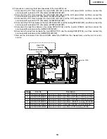
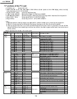
Step
Part No.
Description
1
QCNW-A555WJZZ
Extension Cable 20-pin Main (SC1201)-LCD Panel (CN3)
2
QCNW-A556WJZZ
Extension Cable 50-pin Main (SC1204)-LCD Panel (CN2)
3
QCNW-B784WJZZ
Extension Cable 30-pin Main (SC1202)-LCD Panel (CN1)
4
QCNW-A556WJZZ
Extension Cable 50-pin Main (SC2001)-Analog (SC3403)
5
QCNW-A551WJZZ
Extension Cable 3-pin Analog (P3702)-Inverter (P6502)
6
QCNW-B749WJQZ
Extension Cable 10-pin Main (P701)-Analog (P3704)
»
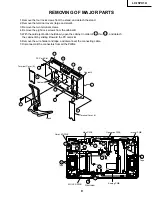
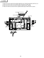
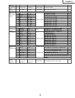
Precautions in servicing the B side (backside) of the main PWB unit
1. Disconnect the FFC from between the main PWB (SC1201) and the LCD panel (CN3), and then connect the
service-specific extension FFC (flat cable) (QCNW-A555WJZZ).
2. Disconnect the FFC from between the main PWB (SC1204) and the LCD panel (CN2), and then connect the
service-specific extension FFC (flat cable) (QCNW-A556WJZZ).
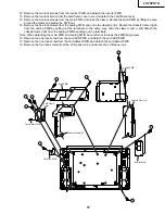
3. Disconnect the FFC from between the main PWB (SC1202) and the LCD panel (CN1), and then connect the
service-specific extension FFC (flat cable) (QCNW-B784WJZZ).
4. Disconnect the FFC from between the main PWB (SC2001) and the analog PWB (SC3403), and then connect the
service-specific extension FFC (flat cable) (QCNW-A556WJZZ).
5. Disconnect the lead from between the analog PWB (P3702) and the inverter (P6502), and then connect the
service-specific extension cable (QCNW-A551WJZZ).
6. Disconnect the lead from between the main PWB (P701) and the analog PWB (P3704), and then connect the
service-specific extension cable (QCNW-B749WJQZ).
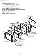
7. Remove the lock screws from the main PWB, detach the PWB from the chassis frame, and then turn it over to
service.
SC2001
SC1204
SC1201
SC1202
P3704
SC3403
P701
P3702
P6502
CN2
CN3
CN1
Inverter PWB
Main PWB
Main PWB
(Side-B)
Analog PWB
4
1
3
7
5
6
2
Summary of Contents for LC-15PX1U
Page 27: ...LC 15PX1U 27 17 16 19 18 15 14 13 12 11 10 INVERTER Unit OPERATION Unit ANALOG Unit ...
Page 30: ...LC 15PX1U 8 7 10 9 6 5 4 3 2 1 A B C D E F G H 30 OVERALL WIRING DIAGRAM ...
Page 31: ...LC 15PX1U 31 17 16 19 18 15 14 13 12 11 10 ...
Page 33: ...33 6 5 4 3 2 1 A B C D E F G H LC 15PX1U SCHEMATIC DIAGRAM Ë OPERATION Unit ...
Page 34: ...LC 15PX1U 8 7 10 9 6 5 4 3 2 1 A B C D E F G H 34 ËMAIN Unit 1 14 ...
Page 35: ...LC 15PX1U 35 17 16 19 18 15 14 13 12 11 10 ...
Page 36: ...LC 15PX1U 8 7 10 9 6 5 4 3 2 1 A B C D E F G H 36 ËMAIN Unit 2 14 ...
Page 37: ...LC 15PX1U 37 17 16 19 18 15 14 13 12 11 10 ...
Page 38: ...LC 15PX1U 8 7 10 9 6 5 4 3 2 1 A B C D E F G H 38 ËMAIN Unit 3 14 ...
Page 39: ...LC 15PX1U 39 17 16 19 18 15 14 13 12 11 10 ...
Page 40: ...LC 15PX1U 8 7 10 9 6 5 4 3 2 1 A B C D E F G H 40 ËMAIN Unit 4 14 ...
Page 41: ...LC 15PX1U 41 17 16 19 18 15 14 13 12 11 10 ...
Page 42: ...LC 15PX1U 8 7 10 9 6 5 4 3 2 1 A B C D E F G H 42 ËMAIN Unit 5 14 ...
Page 43: ...LC 15PX1U 43 17 16 19 18 15 14 13 12 11 10 ...
Page 44: ...LC 15PX1U 8 7 10 9 6 5 4 3 2 1 A B C D E F G H 44 ËMAIN Unit 6 14 ...
Page 45: ...LC 15PX1U 45 17 16 19 18 15 14 13 12 11 10 ...
Page 46: ...LC 15PX1U 8 7 10 9 6 5 4 3 2 1 A B C D E F G H 46 ËMAIN Unit 7 14 ...
Page 47: ...LC 15PX1U 47 17 16 19 18 15 14 13 12 11 10 ...
Page 48: ...LC 15PX1U 8 7 10 9 6 5 4 3 2 1 A B C D E F G H 48 ËMAIN Unit 8 14 ...
Page 49: ...LC 15PX1U 49 17 16 19 18 15 14 13 12 11 10 ...
Page 50: ...LC 15PX1U 8 7 10 9 6 5 4 3 2 1 A B C D E F G H 50 ËMAIN Unit 9 14 ...
Page 51: ...LC 15PX1U 51 17 16 19 18 15 14 13 12 11 10 ...
Page 52: ...LC 15PX1U 8 7 10 9 6 5 4 3 2 1 A B C D E F G H 52 ËMAIN Unit 10 14 ...
Page 53: ...LC 15PX1U 53 17 16 19 18 15 14 13 12 11 10 ...
Page 54: ...LC 15PX1U 8 7 10 9 6 5 4 3 2 1 A B C D E F G H 54 ËMAIN Unit 11 14 ...
Page 55: ...LC 15PX1U 55 17 16 19 18 15 14 13 12 11 10 ...
Page 56: ...LC 15PX1U 8 7 10 9 6 5 4 3 2 1 A B C D E F G H 56 ËMAIN Unit 12 14 ...
Page 57: ...LC 15PX1U 57 17 16 19 18 15 14 13 12 11 10 ...
Page 58: ...LC 15PX1U 8 7 10 9 6 5 4 3 2 1 A B C D E F G H 58 ËMAIN Unit 13 14 ...
Page 59: ...LC 15PX1U 59 17 16 19 18 15 14 13 12 11 10 ...
Page 60: ...LC 15PX1U 8 7 10 9 6 5 4 3 2 1 A B C D E F G H 60 ËMAIN Unit 14 14 ...
Page 61: ...LC 15PX1U 61 17 16 19 18 15 14 13 12 11 10 ...
Page 62: ...LC 15PX1U 8 7 10 9 6 5 4 3 2 1 A B C D E F G H 62 ËANALOG Unit 1 4 ...
Page 63: ...LC 15PX1U 63 17 16 19 18 15 14 13 12 11 10 ...
Page 64: ...LC 15PX1U 8 7 10 9 6 5 4 3 2 1 A B C D E F G H 64 ËANALOG Unit 2 4 ...
Page 65: ...LC 15PX1U 65 17 16 19 18 15 14 13 12 11 10 ...
Page 66: ...LC 15PX1U 8 7 10 9 6 5 4 3 2 1 A B C D E F G H 66 ËANALOG Unit 3 4 ...
Page 67: ...LC 15PX1U 67 17 16 19 18 15 14 13 12 11 10 ...
Page 68: ...LC 15PX1U 8 7 10 9 6 5 4 3 2 1 A B C D E F G H 68 ËANALOG Unit 4 4 ...
Page 69: ...LC 15PX1U 69 17 16 19 18 15 14 13 12 11 10 ...
Page 70: ...70 6 5 4 3 2 1 A B C D E F G H LC 15PX1U ËR C LED Unit ...
Page 71: ...71 6 5 4 3 2 1 A B C D E F G H LC 15PX1U ËCARD LED Unit ...
Page 72: ...72 6 5 4 3 2 1 A B C D E F G H LC 15PX1U ËCARD DETECT Unit ...
Page 73: ...73 6 5 4 3 2 1 A B C D E F G H LC 15PX1U ËINVERTER Unit ...
Page 78: ...LC 15PX1U 8 7 10 9 6 5 4 3 2 1 A B C D E F G H 78 ANALOG Unit Side A ...
Page 79: ...LC 15PX1U 79 17 16 19 18 15 14 13 12 11 10 ...
Page 82: ...82 6 5 4 3 2 1 A B C D E F G H LC 15PX1U INVERTER Unit Side A ...


