6
LC-15A2M
REMOVING OF MAJOR PARTS
1. Insert your finger into the center of the terminal cover
and pull it toward you to detach the terminal cover.
2. Remove the four screws
1
and one screw
2
.
3. Open the cabinet B by approx. 45˚ from the bottom
of the cabinet (stand side).
4. Remove the lead wire from the cable clamp
3
.
5. Remove the power connector
4
.
6. Remove the connector
5
from the light reception
unit.
7. Remove the lead wire from the cable clamp
6
.
8. Remove the speaker connector
7
.
9. Remove the FFC from the FFC connector
8
on the
Main Unit.
10. Remove the connector
9
from the Operation Unit.
11. Remove the right and left speaker connectors
0
on the Terminal Unit.
<<Disassembly of the Main Unit>>
1. Disconnect the flexible cable connectors
q
and
w
from the LCD panel.
2. Disconnect the cable connectors
e
and
r
from
the fluorescent lamp.
3. Remove the four screws
t
.
<<Disassembly of the Terminal Unit>>
1. Remove the cover
u
.
2. Remove the five screws
y
.
3. Remove the two screws
i
. Take them out of the
cabinet holes.
<<Cabinet A side>>
<<Cabinet B side>>
Cabinet A
Terminal Cover
Cabinet B
Summary of Contents for LC-15A2M
Page 14: ...6 5 4 3 2 1 A B C D E F G H 14 LC 15A2M CHASSIS LAYOUT MAIN Unit Side A MAIN Unit Side B ...
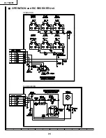
Page 15: ...6 5 4 3 2 1 A B C D E F G H 15 LC 15A2M TERMINAL Unit OPERATION Unit R C RECEIVER Unit ...
Page 16: ...17 LC 15A2M 16 12 11 10 9 8 7 6 5 4 3 2 1 A B C D E F G H BLOCK DIAGRAM ...
Page 17: ...19 LC 15A2M 18 12 11 10 9 8 7 6 5 4 3 2 1 A B C D E F G H Ë MAIN Unit 1 2 ...
Page 18: ...21 LC 15A2M 20 12 11 10 9 8 7 6 5 4 3 2 1 A B C D E F G H Ë MAIN Unit 2 2 ...
Page 19: ...23 LC 15A2M 22 12 11 10 9 8 7 6 5 4 3 2 1 A B C D E F G H Ë TERMINAL Unit ...
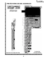
Page 23: ...17 16 19 18 15 14 13 12 11 10 27 LC 15A2M 6 5 4 3 2 1 A B C D E F G H Main Unit Side B ...


