background image

37

LC-15A2M

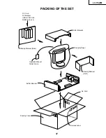
PACKING OF THE SET

Operation Manual
Cable Clamp

Wrapping Paper

Packing Material
(Front)

Packing Material (Rear)

Packing Case

No. Card

Buffer Material

Buffer Material

AC Cord
AC Adapter
Infrared R/C Unit
Batteries (2 pcs.)

Barcode Label

Summary of Contents for LC-15A2M

Page 1: ...AM 16 SCHEMATIC DIAGRAM 18 SHARP CORPORATION SERVICE MANUAL S31Q9LC 15A2M PRINTED WIRING BOARD ASSEMBLIES 25 PARTS LIST Ë ELECTRICAL PARTS 28 MAIN UNIT 28 TERMINAL UNIT 33 OPERATION UNIT 34 R C RECEIVER UNIT 34 Ë CABINET AND MECHANICAL PARTS 34 Ë SUPPLIED ACCESSORIES 36 Ë PACKING PARTS 36 PACKING OF THE SET 37 Page Example of suffix symbol The component parts of this model are partially different ...

Page 2: ...y create shock fire or other hazards WARNING 1 For continued safety no modification of any circuit should be attempted 2 Disconnect AC power before servicing BEFORE RETURNING THE RECEIVER Fire Shock Hazard Before returning the receiver to the user perform the following safety checks 1 Inspect all lead dress to make certain that leads are not pinched and check that hardware is not lodged between th...

Page 3: ...ear 2 5 W Speakers Size Front 3 4 cm 2 pcs Rear φ65 mm 1 pc Voice Coil Impedance Front 32 ohm Rear 6 ohm Antenna Input Impedance 75 ohm unbalanced Video Colour Systems PAL NTSC SECAM Receiving Frequency VHF Channels 44 25 thru 464 25 MHz UHF Channels 471 25 thru 863 25 MHz Weight 3 7 kg w o accessories Accessories R C Batteries AC Adapter AC Cord Operation Manual Cable Clamp Specifications are sub...

Page 4: ...0 degrees Please adjust the angle so that the TV set can be watched most comfortably AUDIO R AUDIO L VIDEO AUDIO R AUDIO L VIDEO S VIDEO COMPONENT Antenna terminal Head phone Power input DC 12V AV IN 2 OUT AV IN 1 POWER TV VIDEO CH VOL VOL CH 8 9 0 DISPLAY LCDTV 1 2 3 4 5 6 7 MENU MPX MENU POWER TV VIDEO CHANNEL SELECT CH Selects next higher channel Selects next lower channel FLASHBACK VOL Returns...

Page 5: ...ns Units mm 1 5 341 4 310 6 138 7 ø 205 0 231 1 307 4 359 0 357 0 45 3 30 3 1 5 156 4 114 5 50 0 46 4 26 0 339 2 124 1 121 1 4 5 66 0 3 0 2 75 12 12 12 12 12 14 0 14 0 14 0 14 0 14 0 14 0 14 0 14 0 14 0 13 0 14 0 35 5 3 0 ...

Page 6: ...e cable clamp 6 8 Remove the speaker connector 7 9 Remove the FFC from the FFC connector 8 on the Main Unit 10 Remove the connector 9 from the Operation Unit 11 Remove the right and left speaker connectors 0 on the Terminal Unit Disassembly of the Main Unit 1 Disconnect the flexible cable connectors q and w from the LCD panel 2 Disconnect the cable connectors e and r from the fluorescent lamp 3 Re...

Page 7: ...ffusion sheet and the reflection polarizing sheet Caution for handling the LCD panel 1 Work in a clean room Humidity 50 or more 2 A worker must wear arm bands 3 Work on a conductive mat 4 Do not expose the unit to shock such as fall or vibration 1 7 8 6 5 4 3 2 1 Shield Case Light Guide Plate Holder Lamp Unit KLMP 0098CEZZ Fixing Angle Reflection Polarizing Sheet LCD Display Unit Condenser Sheet I...

Page 8: ...n on the main power and simultaneously press the inspection process CH and VOL keys to change the mode to the adjustment mode Description The manual adjustment or adjustment through communication with the automatic machine is performed 3 Inspection mode Procedure While holding down the TV VIDEO and MENU keys at the same time turn on the power Description In the ordinary menu select VIDEO ADJUST wi...

Page 9: ...sting conditions Adjusting method 1 Connect the DC voltmeter to pin 49 of SC401 2 Go to the adjustment mode 1 Go to the adjustment mode 1 Receive a B W channel 2 Go to the adjustment mode 3 Select the COM BIAS with MENU key 1 B Adjustment If E2 PROM is replaced IC2004 2 Model setup If E2 PROM is replaced IC2004 3 Counter bias adjustment 1 Adjust the B Adj value to 5 0V 0 02V with VOL or VOL Key Th...

Page 10: ...he tuner and its peripheral parts No Is input at pin 1 of IC402 as specified Check the line in question Yes Check IC402 and its peripheral parts Yes No Are pins 2 and 4 of IC402 at H and L respectively Are pins 65 and 66 of IC2001 at H and L respectively No VIDEO 1 output Yes No Is input at pin 1 of IC402 as specified Check the line in question Yes No Are pins 2 and 4 of IC402 both at L No VIDEO 2...

Page 11: ...e F3701 and F3702 Check S4701 and connection cable Check the secondary side load of T701 Fluorescent lamp Yes No Does F3751 function Yes No Is Pin 34 of IC1201 at H Yes No Are the oscillation waveforms at the primary side of T751 and T752 as specified Yes Replace F3751 No Is input at pin 71 of IC802 as specified Check SC3301 SC line and peripheral parts Yes Check the line IC1201 and its peripheral...

Page 12: ...their peripheral parts No sound from headphone Yes No Is pin 55 of IC2001 at L Check the headphone and its peripheral parts Check Q306 J3410 and their peripheral parts Yes No Is pin 54 of IC2001 at L No Are input at pin 5 as well as output at Pin 2 of IC302 as specified Yes Check the speaker and its peripheral parts Check the line IC901 IC303 and their peripheral parts Muting effect is on Check th...

Page 13: ...TION OF RESISTOR CAPACITOR RESISTOR 1 The unit of resistance Ω is omitted K kΩ 1000 Ω M MΩ 2 All resistors are 5 unless otherwise noted J 5 F 1 D 0 5 3 All resistors are Carbon type unless otherwise noted C Solid W Cement S Oxide Film T Special N Metal Coating CAPACITOR 1 All capacitors are mF unless otherwise noted P pF mmF 2 All capacitors are Ceramic type unless otherwise noted ML Mylar TA Tant...

Page 14: ...6 5 4 3 2 1 A B C D E F G H 14 LC 15A2M CHASSIS LAYOUT MAIN Unit Side A MAIN Unit Side B ...

Page 15: ...6 5 4 3 2 1 A B C D E F G H 15 LC 15A2M TERMINAL Unit OPERATION Unit R C RECEIVER Unit ...

Page 16: ...17 LC 15A2M 16 12 11 10 9 8 7 6 5 4 3 2 1 A B C D E F G H BLOCK DIAGRAM ...

Page 17: ...19 LC 15A2M 18 12 11 10 9 8 7 6 5 4 3 2 1 A B C D E F G H Ë MAIN Unit 1 2 ...

Page 18: ...21 LC 15A2M 20 12 11 10 9 8 7 6 5 4 3 2 1 A B C D E F G H Ë MAIN Unit 2 2 ...

Page 19: ...23 LC 15A2M 22 12 11 10 9 8 7 6 5 4 3 2 1 A B C D E F G H Ë TERMINAL Unit ...

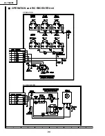
Page 20: ...6 5 4 3 2 1 A B C D E F G H 24 LC 15A2M Ë OPERATION and R C RECEIVER Unit R C RECEIVER OPERATION ...

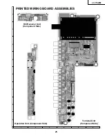
Page 21: ...6 5 4 3 2 1 A B C D E F G H 25 LC 15A2M R C Receiver Unit Component Side Operation Unit Component Side Terminal Unit Component Side PRINTED WIRING BOARD ASSEMBLIES ...

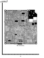
Page 22: ...8 7 10 9 6 5 4 3 2 1 A B C D E F G H 26 LC 15A2M 6 5 4 3 2 1 A B C D E F G H 6 5 4 3 2 1 A B C D E F G H Main Unit Side A ...

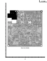
Page 23: ...17 16 19 18 15 14 13 12 11 10 27 LC 15A2M 6 5 4 3 2 1 A B C D E F G H Main Unit Side B ...

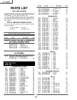
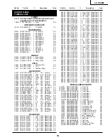
Page 24: ...RH iX3479CEZZ J I C BA IC2002 VHiPST529DM 1 J PST529DMT AE IC2003 VHiTC4W66F 1 J TC4W66F AE IC2004 VHiBR24C08F 1 J BR24C08F E2 AF IC2005 VHiBA7046F 1 J BA7046F AF TRANSISTORS Q201 VS2SC2712Y 1 J 2SC2712Y AB Q202 VS2SC2712Y 1 J 2SC2712Y AB Q203 VSFMY3 1 J FMY3 AB Q204 VS2SC2712Y 1 J 2SC2712Y AB Q302 VS2SA1162Y 1 J 2SA1162Y AB Q303 VSDTC314TK 1 J DTC314TK AC Q304 VSDTC314TK 1 J DTC314TK AC Q305 VSDT...

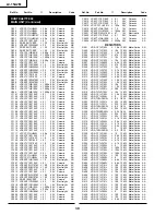
Page 25: ...34 VCKYTV1CF105Z J 1 0 16V Ceramic AB C735 RC EZ0416CEZZ J 330 6 3V Electrolytic AD C736 RC EZ0416CEZZ J 330 6 3V Electrolytic AD C737 RC EZ1339CEZZ J 220 16V Electrolytic AD C738 RC KZ1025CEZZ J 1 0 10V Ceramic AB C740 VCEAPF1EN475M J 4 7 25V Electrolytic AC C741 VCKYTV1CF105Z J 1 0 16V Ceramic AB C746 VCKYCY1EF104Z J 0 1 25V Ceramic AA C747 VCKYTV1HB562K J 5600p 50V Ceramic AA C748 RC EZ1339CEZZ...

Page 26: ...CY1EF104Z J 0 1 25V Ceramic AA C2017 VCKYCY1EF104Z J 0 1 25V Ceramic AA C2018 VCCCCY1HH101J J 100p 50V Ceramic AA C2019 VCKYTV1AB105K J 1 0 10V Ceramic AD C2020 VCKYCY1HB102K J 1000p 50V Ceramic AA C2021 VCEAPF1AW476M J 47 10V Electrolytic AB C2022 VCKYCY1EF104Z J 0 1 25V Ceramic AA C2023 VCKYTV1AB105K J 1 0 10V Ceramic AD C2024 VCKYCY1HB222K J 2200p 50V Ceramic AA RESISTORS R201 VRS CY1JF102J J 1...

Page 27: ... AA R832 VRS CY1JF102J J 1 0k 1 16W Metal Oxide AA R833 VRS CY1JF102J J 1 0k 1 16W Metal Oxide AA R834 VRS CY1JF102J J 1 0k 1 16W Metal Oxide AA R852 VRS CY1JF000J J 0 1 16W Metal Oxide AA R860 VRS CY1JF000J J 0 1 16W Metal Oxide AA R861 VRS CY1JF000J J 0 1 16W Metal Oxide AA R901 VRS CY1JF101J J 100 1 16W Metal Oxide AA R902 VRS CY1JF101J J 100 1 16W Metal Oxide AA R903 VRS CY1JF101J J 100 1 16W ...

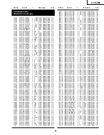
Page 28: ... J 470 1 16W Metal Oxide AA R2033 VRS CY1JF105J J 1 0M 1 16W Metal Oxide AA R2035 VRS CY1JF102J J 1 0k 1 16W Metal Oxide AA R2041 VRS CA1JF101J J 100 1 16W Metal Oxide AA R2042 VRS CY1JF101J J 100 1 16W Metal Oxide AA R2045 VRS CY1JF223J J 22k 1 16W Metal Oxide AA R2047 VRS CY1JF223J J 22k 1 16W Metal Oxide AA R2048 VRS CY1JF332J J 3 3k 1 16W Metal Oxide AA R2049 VRS CY1JF332J J 3 3k 1 16W Metal O...

Page 29: ...etal Oxide AA R3306 VRS CY1JF101J J 100 1 16W Metal Oxide AA R3308 VRS CY1JF000J J 0 1 16W Metal Oxide AA R3310 VRS CY1JF000J J 0 1 16W Metal Oxide AA R3313 VRS CY1JF000J J 0 1 16W Metal Oxide AA R3314 VRS CY1JF101J J 100 1 16W Metal Oxide AA R3315 VRS CY1JF000J J 0 1 16W Metal Oxide AA R3319 VRS TQ2BD750J J 75 1 8W Metal Oxide AA R3321 VRS CY1JF822J J 8 2k 1 16W Metal Oxide AA R3323 VRS CY1JF101J...

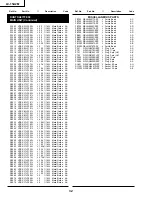
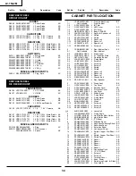
Page 30: ... x1 AB 1 11 VSP4030P 44YD J Speaker x2 AR 1 12 XEBSD20P05000 J Screw x4 AA 2 CCABB2290CE02 J Rear Cabinet Ass y BE 2 1 Not Available Rear Cabinet 2 2 HiNDP5819CESA J Model Label 2 3 HiNDP5679CESA J AV Indication Plate AG 2 4 JBTN 2047CEKA J Operation Button AF 2 5 LANGF9601CEFW J Fixing Metal AK 2 6 LX BZ3425CEFN J Screw x2 AA 2 7 LX BZ3426CEFN J Screw x3 AA 2 8 LX HZ3064CEFF J Screw x7 AA 2 9 PSL...

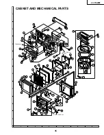
Page 31: ...t OPERATION Unit 4 30 32 23 18 19 20 29 7 21 5 4 1 8 1 7 1 2 1 1 10 1 5 1 12 1 6 1 11 1 6 1 12 41 1 11 1 1 1 3 35 1 4 1 9 1 9 1 9 41 34 37 2 3 2 15 2 8 2 12 2 5 2 9 2 1 2 9 2 14 2 41 2 7 27 2 4 36 43 2 8 2 2 2 11 44 43 2 12 2 13 28 41 41 2 6 3 3 9 3 11 3 2 31 3 6 3 3 3 1 3 8 3 5 3 12 3 7 3 10 3 4 26 TERMINAL Unit R C RECEIVER Unit ...

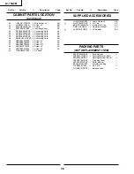
Page 32: ...D26P06000 J Screw x1 AA 41 XEBSD30P08000 J Screw x12 AA 42 XEBSF30P12000 J Screw x2 AA 43 XEBSN30P14000 J Screw x5 AA 44 TLABN0355CEZZ J No Label CABINET PARTS LOCATION Continued SUPPLIED ACCESSORIES LHLDW1028GEZZ J Cable Clamp x2 AB å QACCL0020TAZZ J AC Cord AP RRMCG1558CESA J Infrared R C Unit AV TiNS 7193CEZZ J Operation Manual AU å UADP 0210CEZZ J AC Adapter BH PACKING PARTS NOT REPLACEMENT IT...

Page 33: ... OF THE SET Operation Manual Cable Clamp Wrapping Paper Packing Material Front Packing Material Rear Packing Case No Card Buffer Material Buffer Material AC Cord AC Adapter Infrared R C Unit Batteries 2 pcs Barcode Label ...

Page 34: ...a retrieval system or transmitted in any form or by any means electronic mechanical photocopying recording or otherwise without prior written permission of the publisher SHARP CORPORATION AV Systems Group Quality Reliability Control Center Yaita Tochigi 329 2193 Japan D JAPAN P JAPAN TQ1096 S Mar 2001 Printed in Japan NA KG ...

Reviews: