


10
LC-15A2M
TROUBLE SHOOTING TABLE
No picture
at all
Yes
No
Are inputs
and outputs
of IC802 as
specified?
Chec
k all the settings on the microprocessor’
s
adjust process men
u.
No picture
Chec
k IC802
and its
per
ipher
al
par
ts
.
Yes
No
Are inputs
and outputs
of IC1201 as
specified?
Chec
k
IC1201 and
its per
ipher
al
par
ts
.
Chec
k LCD
panel v
o
ltage
and
wav
e
fo
rm
.
No TV
and
VIDEO 1
output
Yes
No
Are inputs
and outputs
of IC402 as
specified?
Chec
k IC402
and its
per
ipher
al
par
ts
.
No
Is input at pin
(73) of IC802
as specified?
Chec
k IC802,
A
V1 line and
their
per
ipher
al
par
ts
.
No TV
output
Yes
No
Are v
o
ltages
at pins (6),
(7) and (9) of
tuner as
specified?
Chec
k the
po
w
e
r line
.
Yes
No
Is output at
pin (19) of
tuner as
specified?
Chec
k the
tuner and its
per
ipher
al
par
ts
.
No
Is input at pin
(1) of IC402
as specified?
Chec
k the
line in
question.
Yes
Chec
k IC402
and its
per
ipher
al
par
ts
.
Yes
No
Are pins (2)
and (4) of
IC402 at
“H”
and “L
”
respectiv
ely?
Are pins (65)
and (66) of
IC2001 at
“H”
and “L
”
respectiv
ely?
No VIDEO
1 output
Yes
No
Is input at pin
(1) of IC402
as specified?
Chec
k the
line in
question.
Yes
No
Are pins (2)
and (4) of
IC402 both at
“L
”?
No VIDEO
2 output
No
Is input at pin
(74) of IC802
as specified?
Chec
k J3409,
A
V2 line and
their
per
ipher
al
par
ts
.
No S
VIDEO
output
No
Are inputs at
pins (71) and
(72) of IC802
as specified?
Chec
k
SC3301, SY
line
, SC line
and
per
ipher
al
par
ts
.
No
COMPONENT
output
No
Is input at
pins (4), (5),
(6) and (75)
of IC802 as
specified?
Chec
k J3404,
J3405, J3406,
D
VD-Y line
,
CB line
, CR
line and
per
ipher
al
par
ts
.
Are pins (65)
and (66) of
IC2001 both
at “L
”?
Chec
k IC402
and its
per
ipher
al
par
ts
.
Yes
Chec
k the
line in
question.
Yes
Chec
k the
line in
question.
Summary of Contents for LC-15A2M
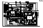
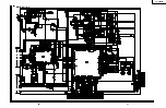
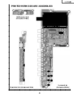
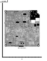
Page 14: ...6 5 4 3 2 1 A B C D E F G H 14 LC 15A2M CHASSIS LAYOUT MAIN Unit Side A MAIN Unit Side B ...
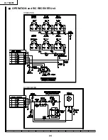
Page 15: ...6 5 4 3 2 1 A B C D E F G H 15 LC 15A2M TERMINAL Unit OPERATION Unit R C RECEIVER Unit ...
Page 16: ...17 LC 15A2M 16 12 11 10 9 8 7 6 5 4 3 2 1 A B C D E F G H BLOCK DIAGRAM ...
Page 17: ...19 LC 15A2M 18 12 11 10 9 8 7 6 5 4 3 2 1 A B C D E F G H Ë MAIN Unit 1 2 ...
Page 18: ...21 LC 15A2M 20 12 11 10 9 8 7 6 5 4 3 2 1 A B C D E F G H Ë MAIN Unit 2 2 ...
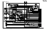
Page 19: ...23 LC 15A2M 22 12 11 10 9 8 7 6 5 4 3 2 1 A B C D E F G H Ë TERMINAL Unit ...
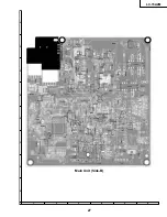
Page 23: ...17 16 19 18 15 14 13 12 11 10 27 LC 15A2M 6 5 4 3 2 1 A B C D E F G H Main Unit Side B ...