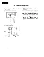
How to prevent
from damages due to static elec-
tricity
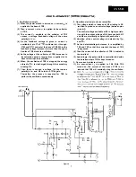
1. When replacing or handling the IC, be sure to put on
your wrist a metal ring (earth ring) that is connected
to ground.
Avoid touching the IC directly by hand as much as
possible.
For the soldering iron and other jigs in use, be sure
to connect them to ground so that their potential is
the same as that of the PWB and/or IC.
The PWB cannot be connected to ground in some
condition although you attempt to attach the IC to
that PWB. In this case, be sure to keep the PWB at the
same potential as ground by touching it by your
hand on which a metal ring put.
When handling the IC, it recommended for you to
wear such clothes as not causing static electricity;
the ones of wool, silk or synthetic fiber should be
avoided. This is important in particular when hand-
ling the IC in a dry environment.
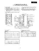
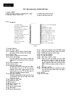
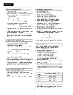
Overall waveform
1. Receive 10 ch. signal.
Connect the sweep output to the tuner TP (test point)
through the specified jig.
Connect the response lead to TP403.
l
Oscilloscope range:
Connect a resistor (100 ohms) to both ends of R229
and short
Note: Keep the lead of the 100 ohm resistor as short
as possible.
J
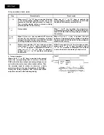
5. Apply DC voltage (about 5V) TP207 (IF-AGC) and
adjust so that the output waveform on oscilloscope is
at
Note: The voltage applied to TP207 should not ex-
ceed 7V in any case.
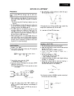
6. Check that the overall waveform is within the speci-
fied range shown below.
If the waveform is out of the specified range, adjust it by
using the IF transformer (IFT) on the tuner.
n
Location of TP and
of the tuner:
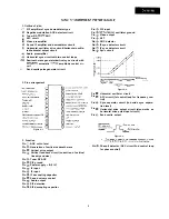
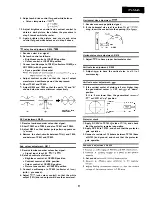
Adjustment of AFT:
1. Receive luminance-order colour bar signal.
Adjust R225 (RF-AGC control) so that normal picture
appears on TV
(Set the band switch at NORMAL position.)
Connect oscilloscope to TP403.
l
Oscilloscope range: 0.5 V/cm AC
l
Sync operation: Horizontal
Adjust the oscillator’s output so that signal beating
observed on oscilloscope.
Adjust the tuning control to have zero beating
oscilloscope as shown in the figure below.
(Set the band switch at VHF position.)
7. Set the band switch at NORMAL position and adjust
T201 to make zero the beating.
9
Summary of Contents for DV-5145
Page 32: ...S H A R P T5157 S MW KY ...


