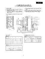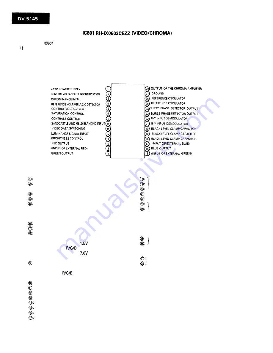
1. Outline of
PAL signal demodulation and R/G/B matrix output
2) White peak limiter control circuit
3) R/G/B mixing circuit included
4) Sand castle pulse processor
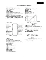
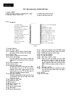
2. Pins arrangement
Figure 5.
3. Circuitry behaviors
Pin
12V power supply
Pin
Generation of ACC detector control voltage
(generation of killer on/off control voltage)
Pin
Chroma input
Pin
Reference voltage for ACC detector
Pin
ACC control voltage
The peak detector ACC works to detect the
voltage which is proportional to the burst signal
level.
Pin
Colour saturation control
Pin
Contrast control
Pin
Sand castle puise input
The sand castle pulse is divided into two pulses;
the first pulse is set at
DC and used for
blanking of the
output signal, and the
second pulse is set at
DC and used for
black level clamping and burst keying.
Pin
Video data switching
Switching between R/G/B input and video input
is performed:
input at High level, video
input at Low level.
Pin
Luminance signal input
Pin
Brightness control
Pin
Red output
Pin
Input of external red
Pin
Green output
Pin
Input of external green
Pin
Blue output
Pin
Input of external blue
Pin
Pin
Pin
Black level clamping (only with R/G/B signal
input) to provide the same black level in both
R/G/B input mode and video mode.
Pin
B-Y input demodulator
Pin
R-Y input demodulator
Pin
Burst phase detector output
Pin
These are used to compare the burst gate
signal with the reference signal coming from
the reference oscillator, so that the resultant
signal in applied to the external low pass filter
(R804, C818) to produce a phase control vol-
tage.
Pin
Pin
Reference oscillator
8.86 MHz of the reference oscillator is halved
to be 4.43 MHz (this makes esier a 90” phase
shift operation).
Pin
Ground
Pin
Chroma output
Summary of Contents for DV-5145
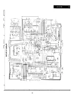
Page 32: ...S H A R P T5157 S MW KY ...


