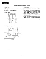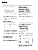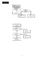
9. Adjust each drive control for good white balance.
l
Colour temperature:
10. Adjust brightness control and contrast control to
obtain a dark picture, then follow the procedure in
step 5 to make white the raster.
11. Again brighten the picture and
adjust
each drive
control for good white balance as in step 9 above.
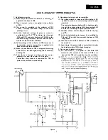
delay line adjustment: R806,
1.
Receive colour bar signal.
Set each control as follows:
l
Brightness control: at CENTER position
l
Colour control: at CENTER position
Connect oscilloscope to TP851 (collector of Q852) on
CRT PWB (with L2 grounded).
l
Sync operation: Horizontal
a l o w
Adjust contrast control so that the top of output
waveform on oscilloscope won’t be depressed.
Short TP401 and TP402.
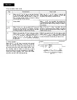
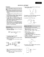
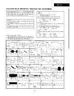
Adjust R806 and T802 so that the parts “A” and “B”
shown below become minimum respectively.
waveform after
adjustment
Horizontal size adjustment:
1. Receive monoscope pattern signal.
2. If the horizontal size is at less than 7% of
ning, insert the socket into the opening (2) of
H-SIZE
Horizontal center adjustment: R618
1. Adjust
to have proper horizontal center.
Vertical size adjustment: R508
1. Adjust
to have the vertical size
be at 8%
o f
overscanning.
Vertical center adjustment:
1. If the vertical center of picture is 5 mm higher than
the geometrical center CRT, set
at “down”
position.
If it is 5 mm lower than the geometrical
set
at “up” position.
mm or
more
mm or
more
d o w n
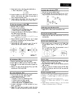
APC adjustment: R802
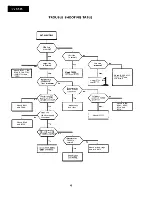
Protector check
1. Receive luminance-order colour bar signal.
2. Short TP803 and TP804, and also TP801 and TP802.
4. Remove the short-circuits between
and T804,
3. Adjust R802 so that barber pole pattern appears on
and between TP801 and TP802.
screen.
1. Apply DC 22V to TP703
side of
and check
that the protector remains inoperative.
3. Connect a resistor of 10 kohms between TP704 (base
2. Apply DC 28V to TP703, and check that the protector
of Q703) and ground, and check that the protector
gets operative.
gets operative.
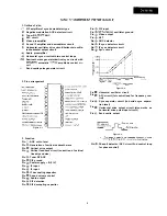
Sub colour adjustment: R817
Sub-sound adjustment: R4008
1. Receive luminance-order colour bar signal.
l
Signal input level: 80
5
2. Set each control as follows:
l
Brightness control: at CENTER position
l
Contrast control: at MAX position
l
Colour control: at CENTER position
l
Picture tone control: at CENTER position
3. Connect oscilloscope to TP850 (collector of
(with
grounded).
4. Adjust
(sub colour control) so that the white
output (75%) and red output will have the same level.
a
3. Set sound
Summary of Contents for DV-5145
Page 32: ...S H A R P T5157 S MW KY ...


