


8-1
8-2
CX51N3/N4
8
CONVERGENCE ADJUSTMENT
NO. Adjustment part
Adjusting procedure and conditions
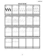
Waveform and others
1
CONVERGENCE
ADJ.
(To be done
after the purity
adjustment.)
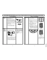
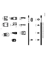
1. Receive the "Crosshatch Pattern" signal.
2. Using the remote controller, call NORMAL
mode.
Static convergence
1. Turn the 4-pole magnet to a proper opening
angle in order to superpose the blue and red
colours.
2. Turn the 6-pole magnet to a proper opening
angle in order to superpose the green colour
over the blue and red colours.
Dynamic convergence
1. Adjust the convergence on the fringes of the
screen in the following steps.
a) Fig. a : Drive the wedge at point "a" and
swing the deflection coil upward.
b) Fig. b : Drive the wedge at point "b" and "c"
and swing the deflection coil downward.
c) Fig. c : Drive the "c" wedge deeper and
swing the deflection coil rightward.
d) Fig. d : Drive the "b" wedge deeper and
swing the deflection coil leftward.
2. Fix all the wedges on the CRT and apply glass
tape over them.
3. Apply lacquer to the deflection yoke lock screw,
magnet unit (purity, 4-pole, 6-pole magnets)
and magnet unit lock screw.
Finally received the Red-only and Blue-only
signals to make sure there is no other colours
on the screen.
Fig. b
Fig. a
Fig. c
Fig. d
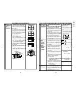
1. Call " SUB-BRI" in service mode. (Receive Cross-
hatch pattern with 5 black level windows)
2. Adjust the " SUB BRIGHT " bus data in order that
the line 1and 2 have the same darkness wherelse
line 3 is one step (data) brighter than line 2. Finally
data minus 1 to make line 1, 2, and 3 are in same
level (darkness).
Remark
1. Before CRT cutoff adjustment, SUB-BRIGHT, DRI-
RS/RW/RC, DRI-GS/GW/GC, DRI-BS/BW/BC,
CUT-R and CUT-G must be INITIAL DATA.
2. CRT Cutoff adjustment must be done inside a dark
room.
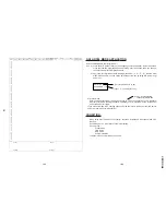
1. Switch TV to VIDEO mode,BLUE BACK OFF, with
NO VIDEO signal.
2. Press R/C to set Picture Normal condition.
3. First, off the screen by adjust screen variable resistor.
*4. Next, checking AKB circuit function by slowly increase
screen variable resistor until colour raster suddenly
on and off (AKB start function).
5. Then continue adjust until retrace line appear.
6. Finally, slowly decrease the screen variable resistor
until screen retrace line cut off (Not Raster)
Note :
Must confirm the AKB function in set before continue
the next adjustment.
CRT CUT-OFF, BACKGROUND AND SUB-CONTRAST ADJUSTMENT
NO. Adjustment part
Adjusting procedure and conditions
Waveform and others
1
2
SUB-
BRIGHTNESS
ADJUSTMENT
(I
2
C BUS
CONTROL)
Line 3 is one step (data) brighter than line 2
CRT CUTOFF
ADJUSTMENT
(I
2
C BUS
CONTROL)
3
WHITE
BALANCE
SERVICE
MODE ADJ.
(I
2
C BUS
CONTROL)
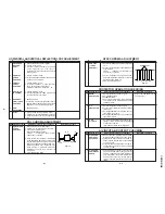
1. Receive the "WHITE" pattern with BURST signal.
2. Press R/C to set Picture NORMAL condition.
3. Connect the DC miliammeter between TP602 (-)
TP603 (+).
4. Check Beam current should be around 1100
µ
A.
5. Set it to service mode and adjust the DRI-GS, & DRI-
BS data to have a colour temperature of 12300
°
K (
white ). * Note .
6. Receive "WHITE" pattern, WITH BURST signal, and
set BRIGHTNESS Y by generator, to **10 cd/m2
(MINOLTA CA-100) by reducing LUMINATE Y sig-
nal.
7. Adjust "CUT-R" & "CUT-G" to get desired colour tem-
perature #. Then go back NORMAL mode (HIGH
BRIGHT**) to check colour temperature.
If out of range, back to 1.
Note:This adjustment must be done after warm-
ing up the unit for 30 minutes or longer with
a beam current over 700
µ
A.
* Adjust DRI-GC/GW, DRI-BC/BW as following DATA,
after finishing DRI-BS and DRI-GS DATA ADJUST-
MENT.
DRI-RW = 32 (FIXED), DRI-RS = 32 (FIXED)
DRI-BC = "DRI-BS"
(For 12300
°
K Condition)
# 12300
°
K
X : 0.272
Y : 0.275
(MINOLTA COLOUR ANALYZER CA-
100)
*Note: Above Data can be UP/DOWN
by Volume key.
LOW
HIGH
10cd/m2
120cd/m2
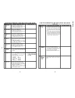
4
Max.
beam check
1. Receive the "Monoscope Pattern" signal.
2. Press R/C to set Picture NORMAL condition.
3. Connect the DC miliammeter between TP603 (+) &
TP602 (–).
(Full Scale: 3 mA Range)
4. Beam current must be within 1100
±
100
µ
A.
1 2 3 4 5
RGB
BGR
R
G
B
R
G
B
B
G
R
B
G
R
RGB
BGR
Lacquer
Wedge "a"
Wedge
"b"
Wedge
"c"
About
100
°
About
100
°
t
3.2Vdc
0
*Alternative Procedure
(1) Step (1), (2), (3) and (4) are same
as beside procedure.
(2) Then continue adjust until retrace
line appear and make sure the col-
our appear whether red, green or
biue.
(3) Connect the oscilloscope to related
test points as below which is based
on colour appear at (2) RED = TP47R,
GREEN =TP47G, BLUE = TP47B
(4) Then adjust Screen VR until the tip
of signal reach (3.2Vdc)
1 2 3 4 5
1
2
* 12300
°
K DRI-GW="DRI-GS"-7
DRI-BW="DRI-BS"-7
DRI-GC="DRI-GS"-7
DRI-RC=25
4-pole magnet
6-pole magnet
CRT neck
20mm
Lacquer
Purity magnet
Summary of Contents for CX51N3
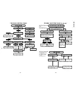
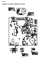
Page 20: ...20 CX51N3 N4 MODEL CX51N3 CHASSIS LAYOUT ...
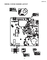
Page 21: ...21 CX51N3 N4 MODEL CX51N4 CHASSIS LAYOUT ...
Page 22: ...22 CX51N3 N4 BLOCK DIAGRAM MAIN BLOCK ...
Page 23: ...23 CX51N3 N4 ...
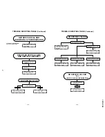
Page 24: ...24 CX51N3 N4 BLOCK DIAGRAM CRT UNIT BLOCK DIAGRAM L3 ...
Page 25: ...25 CX51N3 N4 BLOCK DIAGRAM HEADPHONE UNIT BLOCK DIAGRAM BURST UNIT BLOCK DIAGRAM ...
Page 26: ...27 CX51N3 N4 A B C D E F G H I J 1 2 3 4 5 6 7 8 9 10 CRT UNIT SCHEMATIC DIAGRAM ...
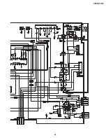
Page 27: ...28 CX51N3 N4 A B C D E F G H I J 1 2 3 4 5 6 7 8 9 10 MAIN UNIT CX51N3 ...
Page 28: ...29 CX51N3 N4 10 11 12 13 14 15 16 17 18 19 ...
Page 29: ...30 CX51N3 N4 MAIN UNIT CX51N4 A B C D E F G H I J 1 2 3 4 5 6 7 8 9 10 ...
Page 30: ...31 CX51N3 N4 10 11 12 13 14 15 16 17 18 19 ...
Page 31: ...32 CX51N3 N4 A B C D E F G H I J 1 2 3 4 5 6 7 8 9 10 HEADPHONE UNIT ...
Page 32: ...33 CX51N3 N4 A B C D E F G H I J 1 2 3 4 5 6 7 8 9 10 BURST UNIT ...


