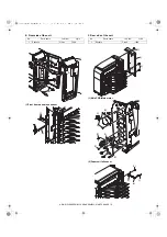

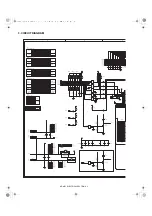
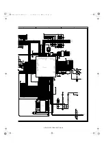

AR-MS1 ELECTRICAL SECTION 8-4
GSOL7
GSOL6
GSOL5
GSOL4
GSOL3
GSOL2
GSOL1
EXIN4
EXIN5
EXIN6
MPPD1/
MPPD2/
MPPD3/
MPPD4/
MPPD5/
MPFD5
MPFD6
MPFD7
MPFD8
EXIN3
EXIN8
EXIN7
EXIN2
EXIN1
PID/
DOPD/
MDD1/
+24VMN
MPFD4
MPFD3
MPFD2
MPFD1/
MMCK
MME
MMLK/
LED
DSR-FIN2
RXD-FIN2/
DTR-FIN2
RES-FIN2/
FGS-FIN
TXD-FIN2/
A6
A14
A2
A1
D7
A7
A15
A8
A1
A4
D1
D5
A0
A10
A13
A5
A11
D6
A9
A12
A3
D0
D2
A2
A0
A3
A0
A1
A2
A3
A5
A6
A7
A4
D0
D1
D2
D4
D5
D6
D7
A8
A9
A10
A11
A12
A13
A14
A15
D3
D3
D4
RD
CE
22
VCC
32
VPP
1
D7
21
D6
20
D5
19
D4
18
D3
17
D2
15
D1
14
D0
13
PGM
31
OE
24
NC
30
A16
2
A15
3
A14
29
A13
28
A12
4
A11
25
A10
23
A9
26
A8
27
A7
5
A6
6
A5
7
A4
8
A3
9
A2
10
A1
11
A0
12
GND
16
.
1
.
2
.
3
COM
9
I1
1
I2
2
I3
3
I4
4
I5
5
I6
6
I7
7
GND
8
O1
16
O2
15
O3
14
O4
13
O5
12
O6
11
O7
10
1
8
2
7
3
6
4
5
1
8
2
7
3
6
4
5
1
8
2
7
3
6
4
5
1
8
2
7
3
6
4
5
1
8
2
7
3
6
4
5
1
8
2
7
3
6
4
5
1
8
2
7
3
6
4
5
1
8
2
7
3
6
4
5
1
8
2
7
3
6
4
5
1
8
2
7
3
6
4
5
1
8
2
7
3
6
4
5
1
8
2
7
3
6
4
5
.
1
.
2
.
3
.
1
.
2
.
3
.
1
.
2
.
3
.
1
.
2
.
3
.
1
.
2
.
3
..
B
2
E
1
C
3
B
2
E
1
C
3
1
8
2
7
3
6
4
5
P14/AN14
1
P15/AN15
2
P16/AN16
3
P17/AN17
4
AVss
5
P130/ANO0
6
P131/ANO1
7
AVref1
8
P70/SI2/RXD
9
P71/SO2/TXD
10
P72/SCK2/ASCK
11
Vss
12
P20/SI1
13
P21/SO1
14
P22/SCK1
15
P23/STB
16
P24/BUSY
17
P25/SI0/SB0
18
P26/SO0/SB1
19
P27/SCK0
20
A0
21
A1
22
A2
23
A3
24
A4
25
A5
26
A6
27
A7
28
AD0
29
AD1
30
AD2
31
AD3
32
AD4
33
AD5
34
AD6
35
AD7
36
A8
37
A9
38
A10
39
A11
40
A12
41
A13
42
Vss
43
A14
44
A15
45
P60
46
P61
47
P62
48
P63
49
RD
50
WR
51
P66/WAIT
52
ASTB
53
P100/TI5/TO5
54
P101/TI6/TO6
55
P102
56
P103
57
P30/TO0
58
P31/TO1
59
P32/TO2
60
P33/TI1
61
P34/TI2
62
P35/PCL
63
P36/BUZ
64
P37
65
P90
66
P91
67
P92
68
P93
69
P94
70
P95
71
P96
72
P120/RTP0
73
P121/RTP1
74
P122/RTP2
75
P123/RTP3
76
P124/RTP4
77
P125/RTP5
78
P126/RTP6
79
P127/RTP7
80
IC
81
X2
82
X1
83
Vdd
84
XT2
85
XT1/P07
86
RESET
87
P00/INTP0/TI00
88
P01/INTP1/TI01
89
P02/INTP2
90
P03/INTP3
91
P04/INTP4
92
P05/INTP5
93
P06/INTP6
94
AVdd
95
AVref0
96
P10/ANI0
97
P11/ANI1
98
P12/ANI2
99
P13/ANI3
100
1
8
2
7
3
6
4
5
1
8
2
7
3
6
4
5
1
8
2
7
3
6
4
5
1
8
2
7
3
6
4
5
1
8
2
7
3
6
4
5
1
8
2
7
3
6
4
5
1
8
2
7
3
6
4
5
1
8
2
7
3
6
4
5
1
8
2
7
3
6
4
5
1
8
2
7
3
6
4
5
1
8
2
7
3
6
4
5
1
8
2
7
3
6
4
5
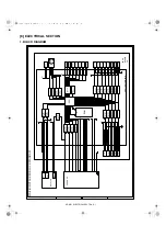
CNE-7
MME/
CNE-9
MMCK/
CNE-8
MMLK/
IC2
M27C1001
X1
4.91MHz
CND-15
GSOL1/
CNC-15
GSOL2/
CNC-9
GSOL3/
CNC-3
GSOL4/
CNB-15
GSOL5/
CNB-9
GSOL6/
CNB-3
GSOL7/
IC3
TD62003AP
C29
R26
4.7KJ
C31
222Z/50V x 2
R29
4.7KJ
C28
222Z/50V x 2
C30
DOPD/
CND-28
PID/
CND-29
MPPD5/
CND-12
C25
MPPD1/
CND-23
C4
222Z/50V x 5
MPPD2/
CND-5
C3
C2
MPPD3/
CND-6
C1
MPPD4/
CND-11
R5
10KJ
R6
10KJ
C33
473Z/16V
RN8
10KJ x4
RN16
10KJ x4
RN9
10KJ x4
RN7
10KJ x4
RN6
10KJ x4
RN10
10KJ x4
RN11
10KJ x4
RN3
10KJ x4
RN1
10KJ x4
RN4
10KJ x4
RN5
10KJ x4
RN17
10KJ x4
R20
4.7KJ
D111
DAN202K
D110
DAN202K
D108
DAN202K
D109
DAP202K
D107
DAP202K
R4
10K
R12
10K
R19
10KJ
R23
10KJ
R14
4.7KJ
R28
4.7KJ
R27
4.7KJ
CNE-4
+24VM
R39
10KJ
C32
222Z/50V
R31
4.7KJ
CP1
RXD
C13
C15
C16
C14
222Z/50V x 8
CNE-5
+24VM
D1
1SS133
D2
1SS133
D5
1SS133
D3
1SS133
R30
4.7KJ
R25
4.7KJ
DTR108
DTC114YKA
DTR107
DTC114YKA
R35
10KJ
RN2
10KJ x4
IC1
uPD78070AGC-7EA
RN24
10KJ x4
RN14
10KJ x4
R38
10KJ
RN12
10KJ x4
RN25
10KJ x4
RN23
10KJ x4
RN22-18
120J x 20
RN15
120J X 4
RN13
10KJ x4
R34
100J
C34
222Z/50V
+24V
+5V
+5V
+5V
+5V
+24V
VDD
VDD
+5V
+5V
+5V
+5V
5V
+5V
EXOUT3
EXOUT1
EXOUT2
FAN
C
C
D
D
E
E
E
D
C
B
A
( !"#$%


