background image

AR-203E/5420/M200/M201  USER PROGRAM  12 - 1

[12] USER PROGRAM

The conditions of factory setting can be changed according to the
use conditions.

1. Functions that can be set with user 

programs

Toner save mode

Reduces toner consumption by approximately 10%.

Power save modes

The unit has two power save modes of operation: preheat mode
and auto power shut-off mode.

Preheat mode

When the unit enters the preheat mode, the power save (

) indi-

cator will light up and other indicators will remain on or off as
before. In this condition, the fuser in the unit is maintained at a
lower heat level, thereby saving power. To copy from the preheat
mode, make desired copier selections and press the start (

)

key using the normal copying procedure.

Auto power shut-off mode

When the unit enters the auto power shut-off mode, the power
save (

) indicator will light up and other indicators except the

ONLINE indicator will go out. The auto power shut-off mode saves
more power than the preheat mode but requires a longer time
before starting copying. To copy from the auto power shut-off
mode, press the start (

) key. Then make desired copier selec-

tions and press the start (

) key using the normal copying proce-

dure.

Auto clear

The unit returns to the initial settings a preset amount of time after
the end of job.

This preset amount of time (auto clear time) can be changed.

Resolution of AUTO & MANUAL mode

You can set the copy resolution used for AUTO and MANUAL
(

) exposure mode.

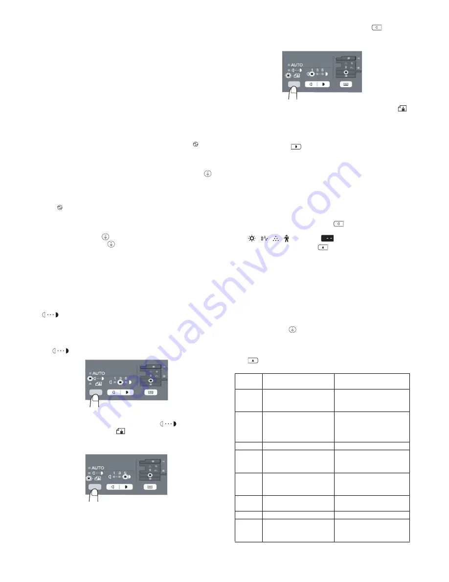
2. Toner save mode (AR-203E/5420)

1) Press the exposure mode selector key to select the MANUAL

(

) mode.

2) Press and hold down the exposure mode selector key for

approximately 5 seconds. The MANUAL (

) indicator will

go out and the PHOTO (

) indicator will begin to blink. The

light and dark indicator marked "5" will light up, indicating the
standard toner mode is active.

3) To enter the toner save mode, press the light (

) key. The

light and dark indicator marked "1" will light up, indicating the
toner save mode is selected.

4) Press the exposure mode selector key. The PHOTO (

)

indicator will stop blinking and light up steadily. The light and
dark indicator marked "3" will light up. The toner save mode is
now active.

Note: To return to the standard mode, repeat the procedure but

use the dark (

) key to select exposure level "5" in step

3).

3. User programs (AR-203E/5420)

The user programs allow the parameters of certain functions to be
set, changed, or canceled as desired.

Set the power save modes, auto clear time, preheat mode, 
SPF automatic original discharge time, resolution of AUTO & 
MANUAL mode and reset factory setting.

1) Press and hold down the light (

) key simultaneously for

more than 5 seconds until all the alarm indicators 
(

) blink and "

" appears in the display.

2) Use the left copy quantity (

) key to select a user program

number (1: Auto clear time, 2: Preheat mode, 3: Auto power
shut off mode, 4: Auto power shut off timer, 6: SPF automatic
original discharge time, 10: Resolution of AUTO & MANUAL
mode, 21: Reset factory, 24: Prevention of OC copies when
the SPF is up function, 25: Copy effective paper width setting
function (Bypass tray), 26: Copy effective paper width setting
function (Tray), 28: Selection of copy start state (Polygon rota-
tion on/off), 29: Fusing temperature setting when the bypass
tray is used). The selected number will blink in the left side of
the display.

3) Press the start (

) key. The entered program number will be

steadily lit and the currently selected parameter number for the
program will blink on the right side of the display.

4) Select the desired parameter using the right copy quantity

(

) key. The entered parameter number will blink on the

right of the display.

Program 

No.

Mode

Parameters

1

Auto clear time

 10 sec., 2 

 30 sec., 

*3 

 60 sec., 4 

 90 sec., 

 120 sec., 6 

 OFF

2

Preheat mode

*1 

 30 sec., 2 

 60 sec., 

 5 min., 4 

 30 min., 

 60 min., 6 

 120 min., 

 240 min.

3

Auto power shut off mode

*1 

 ON, 2 

 OFF

4

Auto power shut off timer

*1 

 5 min., 2 

 30min., 

 60 min., 4 

 120 min., 

 240 min.

6

SPF automatic original 
discharge time

 5 min., *2 

 30 min., 

 60 min., 4 

 120 min., 

 240 min., 6 

 OFF

10

Resolution of AUTO & 
MANUAL mode

*1 

 300dpi, 2 

 600dpi

21

Reset factory

 YES, *2 

 NO

24

Prevention of OC copies 
when the SPF is up 
function

*1 

 ON, 2 

 OFF

Summary of Contents for AR-203E X

Page 1: ...DIGITAL MULTIFUNCTIONAL SYSTEM DIGITAL COPIER AR 203E AR 203E X AR M200 AR M201 MODEL AR 5420 The descriptions of the AR 203E X are same as those of the AR 203E unless otherwise specified 1 GENERAL 1 1 2 SPECIFICATIONS 2 1 3 CONSUMABLE PARTS 3 1 4 EXTERNAL VIEWS AND INTERNAL STRUCTURES 4 1 5 UNPACKING AND INSTALLATION 5 1 6 COPY PROCESS 6 1 7 OPERATIONAL DESCRIPTIONS 7 1 8 DISASSEMBLY AND ASSEMBLY...

Page 2: ...serting wedges or other items into the switch slot LASER WAVE LENGTH 770 795nm Pulse times 12 88µs 12 88ns 7mm Out put power MAX 0 2mW CAUTION INVISIBLE LASER RADIATION WHEN OPEN AND INTERLOCKS DEFEATED AVOID EXPOSURE TO BEAM VORSICHT UNSICHTBARE LASERSTRAHLUNG WENN ABDECKUNG GEÖFFNET UND SICHERHEITSVERRIEGELUNG ÜBERBRÜCKT NICHT DEM STRAHL AUSSETZEN VARO AVATTAESSA JA SUOJALUKITUS OHITETTAESSA OLE...

Page 3: ...able only to the 220V model 230V model and 240V model VAROITUS LAITTEEN KÄYTTÄMINEN MUULLA KUIN TÄSSÄ KÄYTTÖOHJEESSA MAINITULLA TAVALLA SAATTAA ALTISTAA KÄYTTÄJÄN TURVALLISUUSLUOKAN 1 YLITTÄVÄLLE NÄKYMÄTTÖMÄLLE LASERSÄTEILYLLE VARNING OM APPARATEN ANVÄNDS PÅ ANNAT SÄTT ÄN I DENNA BRUKSANVISNING SPECIFICERATS KAN ANVÄNDAREN UTSÄTTAS FÖR OSYNLIG LASERSTRÅLNING SOM ÖVERSKRIDER GRÄNSEN FÖR LASERKLASS ...

Page 4: ...ts 5 9 B Precautions at installation 5 9 C Attachment method 5 9 6 COPY PROCESS 1 Functional diagram 6 1 2 Outline of print process 6 2 3 Actual print process 6 2 7 OPERATIONAL DESCRIPTIONS 1 Outline of operation 7 1 2 Scanner section 7 2 A Scanner unit 7 2 B Optical system 7 2 C Drive system 7 2 3 Laser unit 7 3 A Basic structure 7 3 B Laser beam path 7 3 C Composition 7 3 4 Fuser section 7 3 A G...

Page 5: ...mulation mode 10 1 2 Key rule 10 1 3 List of simulations 10 1 4 Descriptions of various simulations 10 3 5 Trouble codes 10 40 A Trouble codes list 10 40 B Details of trouble codes 10 41 11 MAINTENANCE 1 Maintenance table 11 1 2 Maintenance display system 11 1 3 Remaining toner indication 11 1 12 USER PROGRAM 1 Functions that can be set with user programs 12 1 2 Toner save mode AR 203E 5420 12 1 3...

Page 6: ...h USB E SORT Electronic sort function Duplex Auto duplex copy print function Shifter Job separator function USB Interface port USB RJ45 Interface port Network FAX FAX function AR FX13 External NIC AR NB2A Descriptions of table Standard provision No function or no option available Opt Option Item Model CPM A4 PPM A4 SB MB 2 Tray SPF R SPF Color Scanner GDI printer SPLC printer E SORT Duplex Shifter...

Page 7: ...15 21 lbs Paper feed capacity 250 sheets Kinds Standard paper specified paper recycled paper Remark User adjustment of paper guide available Multi bypass paper feed section Paper size 8 1 2 x 14 8 1 2 x 11 8 1 2 x 5 1 2 3 1 2 x 5 1 2 Landscape Paper weight 15 34 5 lbs Paper feed capacity 50 sheets Kinds Standard paper specified paper recycled paper OHP Label Envelop Single copy Remark User adjustm...

Page 8: ...xed magnification ratios AR 203E 5420 3 Reduction 2 Enlargement AB system 50 70 86 100 141 200 Inch system 50 64 78 100 129 200 AR M200 M201 1 4 Reduction 3 Enlargement AB system 25 50 70 86 100 141 200 400 Inch system 25 50 64 78 100 129 200 400 Zooming magnification ratios 25 400 376 steps in 1 increments 50 200 when using SPF 151 steps in 1 increments Manual steps manual photo 5 steps Copy spee...

Page 9: ...pport No Resolution 600dpi 1 Supported OS Windows 98 Me Windows 2000 Professional Windows XP Home Edition Professional Windows Vista WHQL support Yes 2 Application Status window Type Flat Bed Color Scanner Scanning system Original table SPF RSPF Light source 3 CCDs RGB sensor scanning by lighting white lamp 2 pcs of CCFL Resolution Optical 600 x 1200dpi Setting range 50 9600dpi Preview resolution ...

Page 10: ...ight 170g 10 250K 25K x 10Pcs AR 208CD One carton of the AR 208CD includes 10 developers 3 Drum kit Drum 1 25K AR 152DR One carton of the collective package includes 10 units of the AR 152DR Drum fixing plate 1 No Name Content Life Product name Packing form 1 Toner cartridge Black Toner Toner Net Weight 243g 10 80K 8K x 10Pcs AR 208ET A4 6 document One carton of the AR 208ET includes 10 toner cart...

Page 11: ...drum cartridge shows the date of production SOCC production 1 The production control label is not attached to the cartridge of a China product Humidity RH 85 60 20 10 C 30 C 35 C Humidity RH 90 60 15 25 C 30 C 40 C Humidity RH 90 20 5 C 45 C Production month Production day Destination code Dealer distributor OEM etc Production place SOCC Fixed to B End digit of year Version No Production month Pro...

Page 12: ... copier 2 Keep holding Toner lever and 3 Carefully pull out Toner unit from the copier 4 Put Toner unit in a collection bag immediately after removing it from the copier Note Never carry exposed Toner unit Be sure to put it in the col lection bag Sub lot Production day Production month End digit of year Production place 1 3 2 ...

Page 13: ...6 Multi bypass tray 7 Side cover 8 Side cover open button 9 Bypass tray paper guides 10 Paper output tray 11 Paper output tray extension 12 Power switch 13 Handle 14 Power cord 1 Front cover 2 Side cover 3 Fusing unit release lever 4 Transfer charger 5 Charger cleaner Interface USB connector AR 203E Interface USB connector AR M200 M201 3 4 5 1 2 7 9 8 6 10 11 12 14 13 3 4 5 2 1 Toner cartridge Dru...

Page 14: ... to check the number of originals that must be returned to the document feeder tray if an original misfeed occurs while using the SPF 8 Display Displays the specified copy quantity zoom copy ratio user program code and error code 9 SCAN key and indicator AR 203E only 2 3 10 ONLINE key and indicator AR 203E only Lights up when the unit is used as a printer and scanner 2 11 Start key and indicator C...

Page 15: ...anned data will be transferred to the application B AR M200 M201 For Europe For SCA SCNZ Asia On Indicates the unit is in a power save mode Blinking Indicates that the unit is initializing when the side cover is opened and closed or the power turned off and on On The SCAN key has been pressed and the unit is in scanner mode Blinking A scan job is being executed from the computer or scan data is st...

Page 16: ...he total count 11 2 SIDED SCAN key 2 SIDED COPY key Press to select the automatic two sided copying mode 12 E SORT SP FUNC key Press to select the sort function 2 IN 1 copy function or margin shift function 13 key key OK ENTER key Press the key or key to select an item in a function setting menu Press the OK ENTER key to enter a selection 14 EXPOSURE key Use to switch from auto exposure adjustment...

Page 17: ...ror base scanner unit 3 Toner motor TM Supplies toner 4 Cooling fan motor VFM Cools the optical fusing section 5 Resist roller solenoid RRS Resist roller rotation control solenoid 6 Paper feed solenoid CPFS1 Cassette Paper feed solenoid 1 7 Multi paper feed solenoid MPFS Multi manual pages feed solenoid 8 Duplex motor DMT Devices the duplex paper transport section AR M201 only 9 Shifter motor SFTM...

Page 18: ... detection H at paper pass 3 PPD2 sensor PPD2 Transmission sensor Paper transport detection 2 L at paper pass 4 Cassette detection switch CED1 Micro switch Cassette installation detection H at cassette insertion 5 PD1 sensor AR M200 M201 PD1 Micro switch Paper width detect H at A4 size or less L at A4 size or more 6 PPD1 sensor PPD1 Transmission sensor Paper transport detection 1 L at paper pass 7...

Page 19: ...PWB MCU Copier control 3 Operation PWB Operation input display 4 High voltage PWB High voltage control 5 CCD sensor PWB For image scanning 6 LSU motor PWB For polygon motor drive 7 TCS PWB For toner sensor control 8 LSU PWB For laser control 9 FAX operation PWB FAX operation input AR FX13 option 10 Power PWB AC power input DC voltage control 11 Modem PWB FAX control AR FX13 option ...

Page 20: ...n of the machine AR M200 M201 5 Main charger Provides negative charges evenly to the drum surface 6 Heat roller Fuses toner on the paper Teflon roller 7 Pressure roller Fuses toner on the paper Silicon rubber roller 8 Drum Forms images 9 Transfer unit Transfers images onto the drum 10 Pickup roller Picks up the manual feed paper In multi feed only 11 Manual paper feed tray Tray for manual feed pap...

Page 21: ...e and current requirements Also make certain the outlet is properly grounded Be sure to allow the required space around the machine for servic ing and proper ventilation 2 Cautions on handling Be careful in handling the copier as follows to maintain the perfor mance of this copier Do not drop the copier subject it to shock or strike it against any object Do not expose the drum cartridge to direct ...

Page 22: ...locking switch hold up the catch in illus tration A and turn the center knob counter clockwise 90 degrees until you hear a click 6 Developer unit installation 1 Open the multi bypass tray and then open the side cover 2 Remove the CAUTION tape from the front cover and remove the two protective pins from the fusing unit by pulling the strings upward one at a time 3 Push gently on both sides of the f...

Page 23: ...Be sure to insert carefully 14 Confirm that Developer unit is completely inserted to the bot tom of the machine fix Developer unit and the machine with a screw 15 Completion of Developer unit installation 7 Toner cartridge installation 1 To prevent against uneven distribution of toner hold Toner unit with both hands and shake it several times horizontally 2 Hold the section of Toner unit shown in ...

Page 24: ...ed as a network printer Scanner driver The scanner driver allows you to use the scanning function of the machine with TWAIN compliant and WIA compliant applications Sharpdesk Excluding AR 203E X Sharpdesk is an integrated software environment that makes it easy to manage documents and image files and launch applica tions Button Manager Button Manager allows you to use the scanner menus on the mach...

Page 25: ...a if a message screen appears asking you for confirmation click Allow 5 The SOFTWARE LICENSE window will appear Make sure that you understand the contents of the software license and then click the Yes button Note You can show the SOFTWARE LICENSE in a different language by selecting the desired language from the language menu To install the software in the selected language continue the installat...

Page 26: ...00 XP and a warning message appears regarding the Windows logo test or digital signature be sure to click Continue Anyway or Yes This completes the installation of the software If you installed Button Manager set up Button Manager as explained in C Setting up Button Manager If you installed Sharpdesk the Sharpdesk setup screen will appear Follow the instructions in the screen to set up Sharpdesk 1...

Page 27: ...used as the default printer make the selections and click the Next button Follow the on screen instructions Caution If you are using Windows Vista and a security warning window appears be sure to click Install this driver software anyway If you are running Windows 2000 XP and a warning message appears regarding the Windows logo test or digital signature be sure to click Continue Anyway or Yes 8 Yo...

Page 28: ...e 2000 1 Click the Start button select Settings and then click Con trol Panel 2 Double click the Scanners and Cameras icon Note If the Scanners and Cameras icon does not appear in Windows Me click view all Control Panel options 3 Select SHARP AR XXXX and click the Properties button In Windows Me right click SHARP AR XXXX and click Prop erties in the pop up menu 4 In the Properties screen click the...

Page 29: ...locking switch must be locked to prevent shipping damage 7 Close the multi bypass tray and the paper output tray extension and attach the packing materials and tape which were removed during installation of the unit 8 Pack the unit into the carton 13 Scanner moisture proof kit If the machine is installed in a highly humid environment you can alleviate dew condensation inside the scanner by install...

Page 30: ...the mylar to the R part the yellow line in the diagram below so that the hole of the metal plate is covered as much as possible Attach along the edge of the projection the yellow line in the diagram below 5 Attach the Optical right hole mylar B at the 2 positions shown in the diagrams below which are at the top of the rear side of the main unit Note The holes should be covered with the mylar Attac...

Page 31: ...steps shown in the diagram so that there will be no gap Press the cushion to make sure all the holes are covered 8 Bend the edge of the Scanner motor lower mylar and stick together 9 Attach the Scanner motor lower mylar at 1 position under the motor attachment plate on the rear side of the main unit Note The mylar should cover the hole under the motor unit Attach matching the hole the yellow mark ...

Page 32: ...agram Attach along with the bent part of the metal plate and align the edge of the mylar with the line shown in the diagram the yel low line in the diagram 13 Attach the Fan housing cushion to the cooling fan at the posi tion shown in the diagram below Cover the top and the right side of the fan housing when you see the fan housing from the backside of the machine Note Please make sure the double ...

Page 33: ...ser beam MG roller Cleaning blade Drum Transfer unit Resist roller Exposure Main high voltage unit Saw tooth Charge Drum Cleaning Cleaning blade Waste toner box Paper release Fusing Separation Heat roller Heater lamp Transfer Transfer charger Transfer high voltage unit Developing Toner Developer Print process Paper transport route Semiconductor laser Manual feed PS roller Focus correction lens Ele...

Page 34: ...ep 5 Cleaning Residual toner on the drum surface is removed and col lected by the cleaning blade Step 6 Optical discharge Residual charge on the drum surface is removed by semiconductor laser beam 3 Actual print process Step 1 DC charge A uniform negative charge is applied over the OPC drum surface by the main charging unit Stable potential is maintained by means of the Scorotron charger Positive ...

Page 35: ...lop ing bias Step 4 Transfer The visible image on the drum surface is transferred onto the print paper by applying a positive charge from the transfer corona to the backside of the print paper Step 5 Separation Since the print paper is charged positively by the transfer corona it is discharged by the separation corona The separation corona is connected to ground Step 6 Cleaning Toner remaining on ...

Page 36: ...charged the carrier is attracted to the drum because of the strong electrostatic force of the drum To avoid this the process is controlled by adjusting the drum potential and the grid potential of the Scorotron charger Basic function Voltage added to the screen grid can be selected high and low To make it easily understood the figure below shows voltage transi tion at the developer unit Start 1 Be...

Page 37: ...ams are radiated through the polygon mirror and various lenses to the OPC drum Printing 7 Electrostatic latent images are formed on the OPC drum according to the laser beams and the latent images are devel oped to be visible images toner images 8 Meanwhile the paper is fed to the image transfer section in synchronization with the image lead edge 9 After the transfer of toner images onto the paper ...

Page 38: ...ete color scanning When PC scanning The resolution is 600dpi When copying only the green component is used to print with the printer The color component for printing can be switched to red or blue by the service simulation Spectrum characteristics of the lamp Spectrum characteristics of the color CCD Optical unit C Drive system The drive system is composed of the scanner motor the pulley gear the ...

Page 39: ...or measurement of the laser writing start point Makes the laser scanning speeds at both ends of the drum same as each other B Laser beam path C Composition Effective scanning width 216mm max Resolution 600dpi Beam diameter 75um in the main scanning direction 80um in the sub scanning direction Image surface power 0 18 0 01mW Laser wavelength 770 795nm Polygon motor section Brushless motor 20 787rpm...

Page 40: ...ded with a fusing resistor in the fusing section to improve transfer efficiency Since the upper heat roller is conductive when using copy paper that contains moisture and the distance between the transfer unit and the fusing unit is short the transfer current may find a path to ground via the copy paper the upper heat roller and the discharg ing brush 5 Paper feed section and paper transport secti...

Page 41: ...ght in contact with a notch on the clutch sleeve stopping rotation of the pick up roller 5 At this time the paper is fed passed the paper entry detection switch PPD1 and detected by it After about 0 15 sec from detection of paper by PPD1 the tray paper feed solenoid PFS turns on so that the clutch sleeve projection comes into contact with the paper feed latch to stop the pick up roller Then the pi...

Page 42: ...ler is pressed to the surface of the paper to start paper feeding 3 When pawl C of the manual paper feed clutch sleeve is engaged with the manual feed latch the manual feed stopper falls and the manual take up roller rises At that time the man ual paper feed roller is rotating 4 The lead edge of the transported paper is pressed on the resist roller by the transport roller Then the paper is stopped...

Page 43: ...tchback operation is per formed To the back copy C Back copy Document transport By switchback operation the document is sent through the upper transport roller and the PS roller to the exposure section where the back surface of the document is exposed The document is sent to the document exit section by the lower transport roller and the paper exit roller The document is sent to the intermediate t...

Page 44: ...are in upside down each other Copy mode without rotation The front and the back are not in upside down 7 Shifter AR M200 M201 Shift width 2 5cm The offset function by the shifter is turned ON OFF by the user pro gram According to the setting offset operation is performed for every job Default ON ...

Page 45: ...the procedure of item 12 4 Remove the main charger When uneven charging occurs clean the screen grid and the sawteeth with an air blower 5 Remove the cleaning blade Note Dispose the cleaning blade which was removed If a cleaning error occurs replace the cleaning blade Recommendable replacement cycle Every 25K Before disassembly be sure to disconnect the power cord for safety 1 Do not disconnect or...

Page 46: ... screwdriver and push it in the clearance between the process frame and the cleaning blade Machine F side Machine R side Normal state of the molt Machine F side Machine R side 9 Attach the moquettes Attach the mocket with slightly pressing section A of the clean ing blade Do not touch the tip of the cleaning blade Do not put the mocket under the cleaning blade Do not put the mocket on the sub blad...

Page 47: ...t the sub blade edge breakage Attach the drum so that its position with the sub blade is as shown 12 Attach the drum cover Note After attaching the drum cover do not make a copy When attaching the drum cover engage the detection gear 20T rib with the 30T gear rib and attach the drum cover to the process frame 13 Insert the process unit into the machine until it is fully engaged C Disassembly proce...

Page 48: ... the screw 2 Remove the spring and remove the charger wire 3 Install a new charger wire by reversing the procedures 1 and 2 At that time be careful of the following items The rest of the charger wire must be within 1 5mm Refer to Fig 1 The spring hook section charger wire winding section must be in the range of the projection section Be careful not to twist the charger wire 2 Operation panel secti...

Page 49: ...four screws and remove the operation PWB AR 203E 5420 AR M200 M201 C Assembly procedure For assembly reverse the disassembly procedure 3 Optical section A List B Disassembly procedure 1 Remove four screws and remove the rear cabinet and the rear cabinet cover 1 1 1 2 1 1 1 1 1 2 3 3 3 3 3 3 3 3 4 NO Part name Ref 1 Copy lamp unit 2 Copy lamp 3 Lens unit 1 3 2 4 2 5 5 5 5 1 1 2 2 1 ...

Page 50: ... 8 Remove the screw and remove the rear cover 9 Remove the table glass 10 Move the carriage to the position indicated on the figure 11 Loosen the screw which is fixing the tension plate 12 Move the tension plate in the arrow direction to release the tension and remove the belt 13 Remove the screw and remove the rod stopper 14 Remove the rod 15 Lift the rear side of the carriage remove the belt and...

Page 51: ...ets to fix the CCD MCU harness to the base plate 6 Pass the core through the CCD MCU harness and fix the core 7 Insert the CCD MCU harness into the MCU PWB 4 Fusing section A List B Disassembly procedure 1 Remove the connectors 3 pcs of the rear cabinet 2 Open the side cover remove two screws and remove the fus ing unit 3 Cut the binding band remove the screw and remove the ther mistor Note Attach...

Page 52: ...ove the fusing cover lower on the right side and open the heat roller section 6 Remove the screw and remove the PPD2 sensor 7 Remove the plate spring on the right and remove the heater lamp 8 Remove the spring and remove the upper separation pawls 3 pcs 9 Remove the E ring and remove the reverse gate 1 2 1 5 5 6 6 4 3 2 1 2 PPD2 sensor 1 2 Heater lamp 3 1 2 2 1 3 ...

Page 53: ...y Continued from procedure 4 5 Remove screws remove the fusing cover and open the heat roller section 6 Remove the C ring and the fusing bearing and remove the heat roller 7 Remove the parts from the heat roller Note Apply grease to the sections specified with 1 Grease JFE552 UKOG 0235FCZZ 8 Remove two screws and remove the thermo unit Note The set temperature of the thermostat differs from that o...

Page 54: ...2 Remove two screws and remove the hinge guide R 3 Disconnect the connector 2 positions 4 Remove five screws and remove the scanner unit 5 Remove the fan duct 6 Remove the connector and the screw and remove the speaker unit When the AR FX13 is installed 7 Remove the connector 8 Remove four screws and remove the FAX PWB unit When the AR FX13 is installed No Part name Ref 1 PPD1 sensor PWB 2 POD sen...

Page 55: ...ffers depending on the model 10 Remove the PWB insulation mylar and remove the paper trans port detection sensor POD 11 Remove two springs and open the intermediate frame unit AR 203E 5420 12 Remove the screw and open the upper paper guide AR M200 M201 13 Remove the roller and remove the belt AR M200 M201 1 1 1 1 2 2 3 2 1 1 2 1 1 2 1 1 2 1 2 ...

Page 56: ...he pawl and remove the roller knob 16 Disengage the pawl and shift the pulley and the bearing 17 Remove the paper exit roller and remove the belt the pulley and the bearing 18 Remove the harness guide 19 Remove two screws and remove the toner motor 20 Remove three screws and remove the DUP motor unit and the belt AR M201 4 2 1 3 1 2 3 4 1 2 1 2 1 1 2 3 ...

Page 57: ...sure release solenoid and the paper feed solenoid 23 Remove four screws and remove the paper guide unit AR 203E 5420 24 Remove four screws and remove the lower paper guide unit AR M200 M201 Note for installation Fit the lower paper guide hole a with the shifter gear hole b so that the black resin c of the shifter unit can be checked 1 1 3 2 1 CAUTION Attach the gears securely 1 AL 2030 only AL 203...

Page 58: ...E ring the gear and the bearing and remove the shifter roller AR M200 M201 28 Disengage the pawl and remove the pulley 29 Shift and remove the shifter unit AR M200 M201 30 Remove four screws and remove the LSU unit Note for assembling the LSU When installing the LSU turn the LSU clockwise and fix with screws in order to provide an attachment backlash in the proper direction Observe the following s...

Page 59: ...r and lift the intermediate frame unit to remove 34 Remove the screw and the E ring and remove the PS semi cir cular earth plate and the PS roller unit 35 Remove the E ring and remove the spring clutch from the PS roller unit 36 Remove three screws and remove the TC front paper guide 5 1 2 3 4 2 2 3 4 1 5 4 4 1 2 3 PS roller unit PS semi circuler earth plate 5 4 4 1 2 3 PS semi circular earth plat...

Page 60: ...ings and remove the clutch unit C Assembly procedure For assembly reverse the disassembly procedure 6 Manual paper feed section A List B Disassembly procedure Multi unit 1 Remove the screw and remove the multi upper cover 1 2 4 5 1 2 3 4 Back Front Clutch unit Paper feed roller No Part name Ref 1 Manual transport roller 2 Cassette detection switch 3 PPD1 sensor PWB 4 Side door detection unit 2 1 ...

Page 61: ...ection unit 3 Remove three screws and remove the multi paper feed upper frame 4 Remove two screws and remove the multi feed bracket unit from the multi paper feed upper frame 5 Remove three E rings and remove the manual paper feed roller B9 1 2 Back Wire treatment 1 2 1 2 2 1 1 2 1 1 1 3 L O C K T O K ...

Page 62: ...lder attachment 1 Attach the pressure plate holder so that the resin section is not covered with the seal M1 N 7 Rear frame section A List B Disassembly procedure 1 Remove four screws and remove the rear cabinet and the rear cabinet cover 2 1 1 2 3 Multi paper feed solenoid No Part name Ref 1 Scanner motor 2 Main motor 3 Exhaust fan motor 4 Main PWB Pressure plate holder Seal M1 N Attachment refer...

Page 63: ... screws and one harness and remove the main motor 7 Remove two screws and one connector and remove the exhaust fan motor Note Be careful of the installing directions of the fan Attach it so that the blowing direction faces outside 8 Disconnect the connectors 9 Remove the five screws and remove the MCU PWB C Assembly procedure For assembly reverse the disassembly procedure 2 2 3 1 2 2 1 2 3 1 2 3 1...

Page 64: ...DV unit section A Developer 1 Remove the screw slide the pawl to the right side and remove the TN guide 2 Remove the screw and remove the DV cover 3 Remove the used developer 4 Supply new developer B DV seal 1 Peel off the old DV seal 2 Clean the attachment surface with alcohol 3 Attach the new DV seal to the reference position No Part name Ref 1 Power PWB 1 1 1 1 2 3 4 4 5 1 1 2 1 2 B X X D C B A...

Page 65: ...ar 2 Remove the screw and remove the DV sensor Clean the sensor A section 10 Duplex motor section AR M201 only A List B Disassembly procedure 1 Remove the rear cabinet 2 Remove two screws 3 Remove the Duplex motor cover 4 Remove the Duplex motor Note When reassembling be sure to engage the Duplex motor gear with the belt on the main body side C Assembly procedure For assembly reverse the disassemb...

Page 66: ... AR M201 only A List B Disassembly procedure 1 Remove four screws 2 Remove the spring and the earth wire 3 Remove the reverse unit 4 Bend the reverse roller and remove it C Assembly procedure For assembly reverse the disassembly procedure No Part name Ref 1 Reverse roller 1 2 3 1 ...

Page 67: ...ing direction copy magnification ratio adjustment mode To select the adjustment mode use the Exposure mode selec tor key or key for the AR M200 M201 In the case of the automatic adjustment when the START switch is pressed the mirror base unit moves to the white plate for shading to scan the width of the reference line calculating the correction value and displaying and storing this value After exe...

Page 68: ...ported for the installing model and skipped for non install ing mode To select the adjustment mode with SIM 50 10 use the Exposure mode selector key The relationship between the adjustment modes and the lighting lamps are as shown in the table below Machine with the multi manual paper feed unit Supported for the installing model and skipped for non install ing mode Copy image dimensions X 100 Orig...

Page 69: ...he void amount becomes zero Default 50 2 Image rear edge void amount adjustment 1 Set a scale to the rear edge section of A4 or 11 x 8 1 2 paper size as shown in the figure below and cover it with B4 or 8 1 2 x 14 paper 2 Execute SIM 50 01 to select the image rear edge void amount adjustment mode The set adjustment value is displayed on the copy quantity dis play 3 Make a copy and measure the void...

Page 70: ...timing The copy density adjustment must be performed in the following cases When maintenance is performed When the developing bias grid bias voltage is adjusted When the optical section is cleaned When a part in the optical section is replaced When the optical section is disassembled When the OPC drum is replaced When the main control PWB is replaced When the EEPROM on the main control PWB is repl...

Page 71: ...LOW output adjust the HIGH output Do not reverse the sequence Procedures 1 Set the digital multi meter range to DC700V 2 Set the positive side of the test rod to the connector CN11 3 GRID of high voltage section of the power PWB and set the negative side to the frame ground power frame 3 Execute SIM 8 2 The main charger output is supplied for 30 sec in the grid voltage HIGH output mode 4 Adjust th...

Page 72: ...aper 2 Set the test chart so that the scale is positioned as shown below in the S D mode and the D S mode 3 Execute simulation 50 18 Select the SPF RSPF memory reverse output position and press START key to make a copy Adjust the setting so that the front edge image loss is less than 4 0 mm in the SPF RSPF mode An increase of 1 in setting represents an increase of 0 1 mm in image loss B Adjusting ...

Page 73: ...n the image Adjust the setting so that the void area is 2 4 mm An increase of 1 in setting represents an increase of 0 1 mm in void area Void position to be checked 5 Automatic black level correction a Cases when the adjustment is required 1 When the main PWB is replaced 2 When the EEPROM in the main PWB is replaced 3 When U2 trouble occurs 4 When repairing or replacing the optical section b Adjus...

Page 74: ...PF installed 02 03 SPF RSPF Motor ON Only the AR 203E M200 M201 with the SPF RSPF installed 06 Resist clutch ON SPF AR 203E only 08 RSPF paper feed solenoid operation check Only the AR M200 M201 with the RSPF installed 09 RSPF reverse solenoid operation check Only the AR M200 M201 with the RSPF installed 03 03 Shifter operation check AR M200 M201 05 01 Operation panel display check 02 Fusing lamp ...

Page 75: ...talled 49 01 Flash ROM program writing mode 50 01 Lead edge image position 06 Copy lead edge position adjustment SPF RSPF Only the AR 203E M200 M201 with the SPF RSPF installed 10 Center offset adjustment Sim No Sub code Operation 50 12 Document off center adjustment 18 Memory reverse position adjustment in duplex copy Only the AR M201 or the AR M200 with the RSPF installed 19 Duplex copy rear edg...

Page 76: ...y is pressed the mirror base performs full scan at the speed of the set magnification ratio During operation the set magnification ratio is displayed After 3sec the mirror base performs full scan again When OK ENTER START key is pressed once the ready lamp remains OFF The mirror home position sensor status is displayed on the Drum replacement required lamp or the copy mode indicator for the AR M20...

Page 77: ... The RSPF paper feed solenoid SPUS repeats ON for 500ms and OFF for 500ms 20 times by the use of the solenoid drive control Bios Operation 09 RSPF reverse solenoid operation check Only the AR M200 M201 with the RSPF installed Function The RSPF reverse solenoid SPFS repeats ON for 500ms and OFF for 500ms 20 times by the use of the solenoid drive control Bios Operation 03 03 Shifter operation check ...

Page 78: ...d When START key is pressed counting is made and the machine goes into the LED ON check mode LED all ON status after 3sec When Clear key is pressed for the first time it is counted When it is pressed for the second time the key check mode is retained as well as when another key is pressed Note in the key input check mode Be sure to press START key at the last If it is pressed on the way the machin...

Page 79: ...hted Enter the copy quantity with the key or Numeric key for the AR M200 M201 and press OK ENTER START key and copying is executed to make the set quantity of copies and the ready state is kept for 3sec and copying is executed again to make the set quantity of copies These operations are repeated To cancel the simulation turn off the power or execute a simulation which executes hardware reset Oper...

Page 80: ...duplex motor Bios to drive the duplex motor in the normal direction paper exit direc tion for 30sec After completion of this process the machine goes into the sub code entry standby mode Operation 02 Duplex motor reverse operation check AR M201 only Function Use the duplex motor Bios to drive the duplex motor in the reverse direction for 30sec After completion of this process the machine goes into...

Page 81: ... Function The currently set code of the maintenance cycle is displayed and the newly set data are saved Enter the code number with key or Numeric key or key for the AR M200 M201 and press START key The entered value is saved and the display returns to the sub code input standby state Operation AR M200 M201 Main code Sub code Contents Details of function operation 1 Initial display 10 00 TONER MOTO...

Page 82: ...installed Function The FAX related counter is displayed Operation Main code Sub code Contents Details of function operation AR M200 M201 1 Initial display AR 203E 5420 The operation is similar to simulation 20 01 22 01 M CNT AR M200 M201 1 Initial display AR 203E 5420 The operation is similar to simulation 20 01 22 02 M CNT PRESET AR M200 M201 1 Initial display AR 203E 5420 The operation is simila...

Page 83: ...de Contents Details of function operation AR M200 M201 1 Initial display AR 203E 5420 The operation is similar to simulation 20 01 22 12 DRUM CNT Code number CRUM type Display item 00 Not set 0 01 BTA A BTA A 02 BTA B BTA B 03 BTA C BTA C 99 Conversion CONVERSION 1 The CRUM type is displayed 22 13 CRUM TYPE 01 BTA A Code number Version Display item 0 Main unit Program MAIN PROG 1 F IMC Program F I...

Page 84: ...ared to 0 and 000 000 is displayed on the LCD display Operation 05 Duplex counter clear AR M201 only Function When OK ENTER START key is pressed the duplex counter value is cleared to 0 and 000 000 is displayed on the LCD display Operation Main code Sub code Contents Details of function operation AR M200 M201 1 Initial display AR 203E 5420 The operation is similar to simulation 20 01 22 18 PRT CNT...

Page 85: ...er counter value is cleared to 0 and 000 000 is displayed on the LCD display Operation 14 SPF RSPF JAM total counter clear Only the AR 203E M200 M201 with the SPF RSPF installed Function When OK ENTER START key is pressed the SPF RSPF JAM total counter value is cleared to 0 and 000 000 is displayed on the LCD display Operation Main code Sub code Contents Details of function operation AR M200 M201 ...

Page 86: ...peration AR M200 M201 26 02 SPF RSPF setup Function When this simulation is executed the current set SPF RSPF is displayed Enter the code num ber corresponding to the desired SPF RSPF and press OK ENTER START key to save the setting Operation 03 Second cassette setup Function When this simulation is executed the current set second cassette is displayed Enter the code number corresponding to the de...

Page 87: ... mark support control is displayed Enter the code number corresponding to the desired CE mark support control and press OK ENTER START key to save the setting Operation The operation is similar to simulation 26 02 37 Cancel of stop at developer life over Function When this simulation is executed the current setting is displayed Enter the code number and press OK ENTER START key to change the setti...

Page 88: ...er ON timing can be adjusted to 236msec 2ms AR M200 M201 For the AR M200 M201 the adjustment can be made individually for each of the following modes Paper lead edge adjustment table is the same as that of the AR 203E 5420 above Front back surface of paper rear edge adjustment table The default 50 of the transfer OFF timing indicates 210msec passed from PPD1OFF The transfer OFF timing can be adjus...

Page 89: ...nction The paper sensor status is displayed on the LCD LED Operation AR M200 M201 Main code Sub code Contents Details of function operation Code Setting Remark 0 0 mm 1 0 5 mm 2 1 0 mm 3 1 5 mm 4 2 0 mm Default 5 2 5 mm Code Setting Remark 6 3 0 mm 7 3 5 mm 8 4 0 mm 9 4 5 mm 10 5 5 mm AR M200 M201 1 Initial display 2 Numeric key 3 OK ENTER START key AR 203E 5420 1 Press key to change the code numb...

Page 90: ...ls Operation The operation is similar to simulation 09 04 43 01 Fusing temperature setting Normal copy Function Used to set the fusing temperature of 3rd or later sheet For 1st and 2nd sheets simulation 43 14 is used When this simulation is executed the current set code number is displayed Press key or Numeric key for the AR M200 M201 to change the setting and press OK ENTER START key to save the ...

Page 91: ...tion is similar to simulation 26 02 14 Fusing start temperature setting Function When this simulation is started the currently set code number is displayed Press key or Numeric key or key for the AR M200 M201 to switch the set ting and press OK ENTER START key to save it to the EEPROM The machine goes to the sub code entry standby mode Operation The operation is similar to simulation 43 01 Main co...

Page 92: ...y Adjustment value 1 99 Operation The operation is similar to simulation 46 01 Main code Sub code Contents Details of function operation Mode Display item AR M200 M201 LED AR M200 M201 Display lamp AR 203E 5420 Default AE mode 300dpi AE COPY mode lamp AE mode lamp 50 TEXT mode 300dpi TEXT PRINT mode lamp TEXT mode lamp 50 PHOTO mode PHOTO SCAN mode lamp PHOTO mode lamp 50 TS mode TEXT 300dpi TSTXT...

Page 93: ...s the exposure adjustment value of normal text stored on the FAX side 2 Enter a 2 digit value as the exposure adjustment value YY is the entered exposure adjustment value 3 Scan is started self print and the LED of START key is turned off 4 Print is started self print After completion of printing returns to 2 display ADJUST EXP AUTO XX ADJUST EXP AUTO YY ADJUST EXP AUTO SCAN YY ADJUST EXP AUTO PRI...

Page 94: ...5 copies become lower contrast too Press Exposure mode selector key or key for the AR M200 M201 to switch the mode The set value of the selected mode is displayed on the LCD display Adjustment value 1 99 No density display on LCD display Operation The operation is similar to simulation 46 01 Main code Sub code Contents Details of function operation 1 Initial display XX is the corresponding exposur...

Page 95: ...umber corresponding to the desired PHOTO image process setting and press Exposure mode selector key or key for the AR M200 M201 to change the mode and write into the EEPROM Operation The operation is similar to simulation 43 01 20 SPF RSPF exposure correction Only the AR 203E M200 M201 with the SPF RSPF installed Function Used to adjust the exposure correction amount in the SPF RSPF mode The adjus...

Page 96: ...ion The operation is similar to simulation 46 19 31 Image sharpness adjustment Function Used to adjust sharpening blurring of image in each mode When this simulation is executed warm up and shading are performed and the current set value is displayed Default 1 Change the set value and press START key to make a copy under the set conditions To change the mode press Exposure mode selector key or key...

Page 97: ...e Purple Red Yellow 2 Yellow Red Green Blue Water blue Purple Specification component Setting No Remark Green 0 Default Red 1 Blue 2 Mode Display item AR M200 M201 LED AR M200 M201 Display lamp AR 203E 5420 Default AE mode including TS AE COPY mode lamp AE mode lamp 0 TEXT mode including TS TEXT PRINT mode lamp TEXT mode lamp 0 PHOTO mode PHOTO SCAN mode lamp PHOTO mode lamp 0 Sharpness adjustment...

Page 98: ...opy is made When the set value is increased by 1 the magnification ratio is increased by 0 1 The adjustment mode can be changed by pressing Exposure mode selector key or key for the AR M200 M201 Adjustment range 1 99 Default 50 When adjusting the RSPF the mode is set to Duplex Single single copies of two sheets are performed For printing regardless of the density mode and the density level Density...

Page 99: ...e LCD LCD DATE WRITING AR M200 M201 During SUM CHECK FLASH ROM SUM CHECK d ON ON ON During BOOT SUM CHECK BOOT SUM CHECK AR M200 M201 During EEPROM SUM CHECK EEPROM SUM CHECK AR M200 M201 Download complete DOWNLOAD COMPLETE 0FF ON OFF OFF Error state E ON OFF OFF AR 203E 5420 1 Data reception error 6 Sum check Loader section 2 Loader function transfer 7 Sum check Boot section 3 FLASH ROM delete 8 ...

Page 100: ...nce Hmm from the paper lead edge to the image print start position Set A 10 x H mm Example Set to 50 When the value of A is increased by 10 the image lead edge is moved to the paper lead edge by 1mm Default 50 4 Set the lead edge void amount to B 50 2 5mm Default 50 When the value of B is increased by 10 the void is extended by about 0 1mm For 25 or less however the void amount is regarded as 0 Th...

Page 101: ...200 M201 When the set value is changed largely the area outside the shading area may be scanned to cause black streaks on the edges When the SPF RSPF is used select the mode for use of the SPF RSPF by 2 SIDED SCAN 2 SIDED COPY key Support for the installation models For non installation models skip For Simplex models skip When printing with the manual paper feed tray use paper of the letter size I...

Page 102: ...t the set value so that the print lead edge is matched Since printing is made from the image data most lately stored in memory to the lead edge data from the print start position the image lead edge adjustment is made by changing the end data position stored in memory by the set value of this simulation Since it is performed by changing the scan end position the image position adjustment is made b...

Page 103: ... key or key for the AR M200 M201 Enter the adjustment value with key or Numeric key for the AR M200 M201 and press START key to save the set value and make a copy Support for the installation models For non installation models skip Operation AR M200 M201 The operation is similar to simulation 46 01 Main code Sub code Contents Details of function operation Mode Display item LED Default Paper rear e...

Page 104: ...rformed again Operation The operation is similar to simulation 46 01 In MANUAL OK ERR display in AUTO 61 03 Polygon motor check HSYNC output check Function When OK ENTER START key is pressed HSYNC is performed and the polygon motor is rotated for 30sec At that time the ZOOM lamp or the COPY mode lamp for the AR M200 M201 is lighted for 100msec every time when HSYNC is detected Operation AR M200 M2...

Page 105: ... adjustment value with key or Numeric key for the AR M200 M201 and press START key The entered value is stored and the machine goes into the sub code entry standby mode Setting range 0 99 Complying with the light quantity stable wait time of 0 99sec Default 15 15sec Operation The operation is similar to simulation 09 04 13 Light quantity stabilization band setting Function When the difference betw...

Page 106: ... and 1 Operation 02 FAX soft SW initializing excluding the adjustment values Executable only when the FAX is installed Function Use to initializing FAX soft SW Operation Main code Sub code Contents Details of function operation Code number Pattern Display item 0 1by2 1 BY 2 1 Grid pattern CHECK 2 White paper WHITE 3 Black background BLACK 1 Initial display Clear key FAX control is terminated 2 Ent...

Page 107: ...2 SRAM SELECT MEMORY 1 3 3 FLASH CHECKING MEMORY MEMORY CHECK RESULT OK MEMORY CHECK RESULT XXXXXXXX SUM NG MEMORY CHECK RESULT XXXXXXXX A BUS NG MEMORY CHECK RESULT XXXXXXXX DATA NG MEMORY CHECK RESULT XXXXXXXX D BUS NG MEMORY CHECK RESULT XXXXXXXX ERASE NG 1 NO SIGNAL 13 7200bps V34 25 2400bps V27ter 2 33600bps V34 14 4800bps V34 26 300bps FLAG 3 31200bps V34 15 2400bps V34 27 2100Hz CED 4 28800...

Page 108: ...V34 20 9600bps V17 32 NO VOICE ANSWER 9 16800bps V34 21 7200bps V17 33 NO RING BACK TONE 10 14400bps V34 22 9600bps V29 34 LINE OFF HOOK 11 12000bps V34 23 7200bps V29 35 LINE ON HOOK 12 9600bps V34 24 4800bps V27ter 1 Initial display 2 2 digit 1 35 with Numeric key key 2sec after Pressing key or key reverses the sequence Clear key FAX control is terminated 3 OK ENTER key Send after setting Clear ...

Page 109: ...after 2sec Every time when key is pressed the second line is changed in the sequence of No 1 2 3 4 5 6 1 When key is pressed the sequence is reversed Clear key FAX control is terminated 3 OK ENTER key Clear key Returns to 1 Initial display SELECT SIGNAL PRESS SELECT SIGNAL 1 6 1 NO SIGNAL SELECT SIGNAL 1 6 6 00001 OUTPUTING SIGNAL MAX PRESS CLEAR TO STOP 1 Initial display 2 key or after 2sec Every...

Page 110: ...XX SEND yyPPS xxms 1 YES 2 NO SENDING yyPPS xxms TERMINATE 1 YES 2 NO TERMINATED Dial test DTMF 1 Initial display Clear key FAX control is terminated 2 Select 2 Select 2 3 Select 1 Select 2 4 Select 1 XXXX Default After deleting with Clear key input can be made 4 OK ENTER key xx indicates HI and yy indicates Low Soft SW Select 2 Returns to 4 display 5 Select 1 HI LO is selected with the signal lev...

Page 111: ... selection is set inside 3 Communication is started after setting the signal send level Clear key Returns to 1 Initial display INPUT DIAL SENDING SIGNAL SSW PRESS CLEAR TO STOP 1 Initial display 2 key or after 2sec Every time when key is pressed the second line is changed in the sequence of 1 2 3 1 When key is pressed the sequence is reversed Clear key FAX control is terminated 3 OK ENTER key When...

Page 112: ...ils of function operation 1 Initial display When a signal is detected the display is changed from NONE to the following CI CNG CED BT DT Flag SDT DTMF Clear key FAX control is terminated CHECKING NONE PRESS CLEAR TO STOP 1 Initial display xx xx xx xxx indicates o clock minute second millisecond Clear key FAX control is terminated COMM TIME xx xx xx xxx msec 1 Initial display 2 key or after 2sec Ev...

Page 113: ...lay 4 Enter o clock in 2 digits 5 Enter minute in 2 digits xx xx is the current value Select 2 Returns to 1 Initial display 6 Select 1 After 2sec returns to 1 Initial display SELECT TO SET 1 DATE 2 TIME xxxx xx xx xxx CHANGE 1 YES 2 NO INPUT YEAR 4 DIGITS ____ __ __ INPUT MONTH 1 12 1998 __ __ INPUT DAY 1 31 1998 01 __ xxxx xx xx xxx STORED 1 YES 2 NO STORED xx xx CHANGE 1 YES 2 NO INPUT HOUR 0 24...

Page 114: ...y defect data abnormality Check and remedy Replace the MCU PWB with new one Main code Sub code Details of trouble E7 01 Content Duplex model memory setup error memory not detected error Detail The memory is not set properly or the memory capacity is not set to the duplex setup 6M Check and remedy Set SIM 26 39 code number to 2 02 Content LSU trouble Detail The BD signal from the LSU cannot be dete...

Page 115: ...talled Cause Thermistor abnormality Control PWB abnormality Fusing section connector disconnection The fusing unit is not installed Check and remedy Check the harness and the connector between the thermistor and the PWB Use SIM 14 to clear the self diagnostic display Main code Sub code Details of trouble H3 00 Content Heat roller high temperature detection Detail The fusing temperature exceeds 240...

Page 116: ...harness MCU PWB abnormality Check and remedy Use SIM 25 01 to check the main motor operations Check connection of the main motor harness connector Replace the main motor Replace the MCU PWB Main code Sub code Details of trouble L4 32 Content Exhaust fan motor lock detection trouble Detail The error detection is started after 2 sec from starting rotation of the exhaust fan motor 1 The continuous ro...

Page 117: ...n Parts 25K 50K 75K 100K 125K Remark Developing Developer DV blade DV side seal F R DV doctor White streaks are made on the image Process peripheral Drum Toner Life 8K Remaining quantity NEAR EMPTY About 12 5 EMPTY LED ON Flash Machine Operation allowed Stop Developer Life 25K LED ON at 25K of the developer count Machine Selection is available between Not Stop and Stop by Service Simulation SIM 26...

Page 118: ...he exposure mode selector key The PHOTO indicator will stop blinking and light up steadily The light and dark indicator marked 3 will light up The toner save mode is now active Note To return to the standard mode repeat the procedure but use the dark key to select exposure level 5 in step 3 3 User programs AR 203E 5420 The user programs allow the parameters of certain functions to be set changed o...

Page 119: ...re and press the OK ENTER key 25 Copy effective paper width setting function Bypass tray 1 Large A4 width LETTER 2 Small B5R width INVOICE 26 Copy effective paper width setting function Tray 1 Large A4 width LETTER 2 Small B5R width INVOICE 28 Selection of copy start state Polygon rotation on off 1 ON 2 OFF 29 Fusing temperature setting when the bypass tray is used 1 Low 2 High Program No Mode Par...

Page 120: ... ON 2 OFF When enabled this function offsets the position of each set of copies in the output tray in copy mode and each print job in printer mode 9 ROTATE ORIG IMAGE AR 208D only 1 ON 2 OFF When two sided copying is performed this function rotates the image on the back of the original This is convenient when binding the copies at the top tablet binding 10 AE TEXT RESOLUTION 1 300dpi 2 600dpi This...

Page 121: ...original will only be printed up to invoice size 28 LSU SETTING 1 ON 2 OFF Select whether copying is only allowed when the polygon motor is rotating or also when the polygon motor is stopped 29 PAPER TYPE 1 PLAIN PAPER 2 HEAVY PAPER Set the temperature of the fusing unit when the bypass tray is used Normally HEAVY PAPER should be selected 30 DISPLAY CONTRAST 1 LIGHTER 2 LIGHT 3 NORMAL 4 DARK 5 DAR...

Page 122: ... Lock detect 8Kbyte 24V 12V 2nd Cassette MainMotor Toner Motor Mirror Motor AR 203E Optional only Polygon Mechanical load Motor CPFS2 Sensor SW PAPD PPD3 PD2 CED2 AC Code LSU KRONOS ASIC 296pin CPU H8S 2321 19 6608MHz EEPROM SDRAM 16Mbyte or 8Mbyte Reset IC SRAM Driver Flash ROM AFE HT82V24 C D S A G C M P X AD 16bits CCD Driver CCFL x 2 Lamp Inverter for CCFL HOME POSITION SENSOR CCD ILX558X CPU ...

Page 123: ...Motor Buzzer Fan Motor 24V 12V 2nd Cassette Main Motor Toner Motor Mirror Motor Mechanical load CPFS2 Sensor SW Polygon Motor PPD3 PD2 CED2 AC Code LSU KRONOS ASIC 296pin CPU H8S 2321 19 6608MHz EEPROM SDRAM 8Mbyte Reset IC SRAM Driver Flash ROM AFE HT86V26 C D S A G C M P X AD 16bits CCD Driver CCFL x 2 Lamp Inverter for CCFL HOME POSITION SENSOR CCD ILX558K CPU CLK 19 6608MHz System Reset SSCG P...

Page 124: ...D D GND TCS DVSEL 24V 5VEN PMD PMRDY PMCLK_A INT24V MMD PGND AFE_DB4 AFE_DB3 CPFS1 1 INT24V PGND MMD 1 2 3 HLN HLL HLL 3 GRID MCFB TC MC BIAS TC 24V 1 SHOLD SYNC INT5V D GND LDEN VIDEO 8 1 2 1 2 D GND 2 3 4 5 1 12VIN 24V FW P GND 24V PR HLOUT P GND EN5V 3 3VIN 5V POFF D GND P GND D GND 3 3VIN PR HLOUT P GND P GND 12VIN 24V FW 24V EN5V 3 3VIN 5V POFF D GND P GND D GND 3 3VIN BC BIAS TC GRIDL MC BIA...

Page 125: ..._V3 LED_V2 F KEYSC3 F KEYSC2 F KEYSC1 F KEYIN4 F KEYIN3 F KEYIN2 F KEYIN7 F KEYIN6 F KEYIN5 1 24VDupMT AFE_DB6 D GND AFE_DB4 AFE_DB3 AFE_SCK mt_at_home AFE_DB5 AC VOUT D GND DVSEL 24V TCS 5VEN CRUMSDA AFE_DB2 1 D GND GND 3 CCD_PHI1 AFE_SEN AFE_SEN ADCLK ADCLK CCD_PHI1 CCD_PHI2 VCL D GND P GND CCD CP GND 3 AFE_SDI BSAMP BSAMP AC VOUT 1 D GND D GND CCD RS CCD RS VSAMP VSAMP CCD TG CCD TG EN5V EN5V D...

Page 126: ... GND 2 1 SRJD SPID 2 DGND 3 LEDSPID 1 SCOD 2 DGND 3 LED_SPPD 3 2 D GND 2 DGND 3 LEDSPPD 3 LEDSRJD 1 SPPD LEDSCOD SRJD 2 DGND 1 6 3 1 3 1 5 COMA 2 4 LED_SRJD 1 LED_SPPD 2 DGND 3 DGND 4 SRJD 5 SPPD 6 LED_SCOD 7 LED_SPID 8 DGND 9 DGND 10 SCOD 11 SPID 12 NC 15 SPMT_1 16 24VSPFSOL 13 24VSPFSOL 17 SPMT_2 18 SPMT_3 14 SPUS 19 SPMT_0 20 24VSPFSOL 21 24VSPFMT 22 SRVC 23 24VSPFMT 24 MCU PWB SRJD SPMT RSPF U...

Page 127: ... section MMCLK Main motor Clock signal to the polygon motor Main drive section MMD Main motor Polygon motor drive signal Main drive section MPFS Multi bypass solenoid Paper transport section PMD Polygon motor Polygon motor drive signal LSU POFF Low voltage power Output power control Power section PR Heater lamp Power relay control Power section FAX Model FX13 Optional Model Only DHAI 0538QSPZ CN5 ...

Page 128: ...ion LCDDB4 LCD data signal Signal for LCD Operation section LCDDB5 LCD data signal Signal for LCD Operation section LCDDB6 LCD data signal Signal for LCD Operation section LCDDB7 LCD data signal Signal for LCD Operation section LCDE LCD control signal Signal for LCD Operation section LCDRS LCD control signal Signal for LCD Operation section LEDPOD POD sensor power Paper exit section LEDPPD1 PPD se...

Page 129: ...r LSU PMRDY Polygon motor Polygon motor ON OFF detection signal LSU POD POD sensor Paper transport detection Paper exit section PPD1 PPD sensor Paper transport detection Paper transport section PPD2 PPD2 sensor Paper transport detection Fusing section PPD3 PPD3 sensor 2nd CS paper transport detection 2nd cassette section PSL Power save LED Operation section PSW Start button control Operation secti...

Page 130: ...ss 3 NC 4 VCC 5 PC0 A0 6 PC1 A1 7 PC2 A2 8 PC3 A3 9 Vss 10 PC4 A4 11 PC5 A5 12 PC6 A6 13 PC7 A7 14 PB0 A8 15 PB1 A9 16 PB2 A10 17 PB3 A11 18 Vss 19 PB4 A12 20 PB5 A13 21 PB6 A14 22 PB7 A15 23 PA0 A16 24 PA1 A17 25 PA2 A18 26 PA3 A19 27 Vss 28 PA4 A20 IRQ4 29 PA5 A21 IRQ5 30 PA6 A22 IRQ6 31 PA7 A23 IRQ7 32 P67 CS7 IRQ3 33 P66 CS6 IRQ2 34 Vss 35 Vss 36 P65 IRQ1 37 P64 IRQ0 38 P53 ADTRG 102 P52 SCK2 ...

Page 131: ...49 47p TP330 BR42 10kJx4 1 2 3 4 8 7 6 5 BR39 10kJx4 1 2 3 4 8 7 6 5 TP396 TP323 TP381 BR71 10kJx4 1 2 3 4 8 7 6 5 TP348 TP318 TP289 TP87 1 BR54 10kJx4 1 2 3 4 8 7 6 5 TP115 1 R407 N M BR37 33Jx4 1 2 3 4 8 7 6 5 L2 ZJSR5101 223 TP309 R47 33J TP304 TP119 1 TP100 1 TP291 C51 47p TP416 TP446 R27 33J C42 0 1u TP343 C37 47u 16V R28 10KJ C65 0 1u TP363 TP373 C38 0 1u C33 0 1u TP440 TP86 1 C71 N M TP397 ...

Page 132: ...0 A6 19 A7 18 A8 8 A9 7 A10 6 A11 5 A12 4 A13 3 A14 2 A15 1 A16 48 A17 17 DQ0 29 DQ1 31 DQ2 33 DQ3 35 DQ4 38 DQ5 40 DQ6 42 DQ7 44 DQ8 30 DQ9 32 DQ10 34 DQ11 36 DQ12 39 DQ13 41 DQ14 43 DQ15 45 A19 9 NC 10 A18 16 GND 46 GND 27 VCC 37 VPP 13 BYTE 47 OE 28 CE 26 WE 11 RP 12 WP 14 RY BY 15 C89 0 1u R56 10kJ R65 N M TP454 C90 0 1u C91 0 1u TP458 C92 0 1u C93 0 1u TP455 R64 N M C84 0 1u C81 0 1u C94 0 1u...

Page 133: ... 6 1A4 8 2A1 11 2A2 13 2A3 15 2A4 17 1G 1 2G 19 1Y1 18 1Y2 16 1Y3 14 1Y4 12 2Y1 9 2Y2 7 2Y3 5 2Y4 3 VCC 20 GND 10 BR55 33Jx4 1 2 3 4 8 7 6 5 R15 0J TP473 R86 10J IC13 74HC151 D0 4 D1 3 D2 2 D3 1 D4 15 D5 14 D6 13 D7 12 A 11 B 10 C 9 G 7 W 6 Y 5 VCC 16 GND 8 TP463 TP499 TP540 C96 0 1u C99 0 1u R90 33J R100 33J TP524 C104 33p C133 82p R87 33J TP503 R80 10J R74 10J TP500 IC45 NC7ST08M5X 1 2 3 4 5 TP5...

Page 134: ...C102S 1 2 3 R196 10kJ TP555 CP16 0603FA1 5A 0603SFF150FM R112 1 2kF D49 MTZ J22B R364 0J C160 2 2uF 10V TP554 R155 470kJ R109 N M _4 7kJ 1 4W R107 4 3kF R191 4 7kJ R146 1 5kF TP265 R114 10kF R108 N M _47kJ TP618 D34 1SS355 R193 10kJ TP605 R380 N M _1 5kJ TP551 IC24 KID65503F 1B 1 2B 2 3B 3 4B 4 5B 5 6B 6 7B 7 G 8 NC 9 1C 16 2C 15 3C 14 4C 13 5C 12 6C 11 7C 10 TP556 R386 4 7kJ 1 4W D57 RLS 73 D35 1...

Page 135: ... 1kJ IC26 TD62064AF I1 3 NC 4 NC 5 I2 6 NC 10 I3 11 NC 12 NC 13 GND 17 O1 2 O2 7 O3 9 O4 16 COM 1 COM 8 GND 18 I4 14 NC 15 C117 820p R124 30kJ BR59 10kJx4 1 2 3 4 8 7 6 5 C119 820p IC29 TA7291AS Vcc 2 IN1 9 IN2 1 GND 5 OUT2 3 OUT1 7 Vref 8 Vs 6 N C 4 C122 47u 35V D6 MTZ J22B C131 0 1u R127 510J R126 1kJ R132 1J 2W C120 0 1u R125 2kJ C123 0 1u 50V IC28 STA7100M OUT A 1 OUT A 2 OUT A 3 OUT A 4 Vs 13...

Page 136: ...10 KDS226 2 1 3 C163 1000p IC30 KIA7805 IN 1 GND 2 OUT 3 C183 0 1u R182 1kJ C158 0 1u C188 1000p D21 KDS226 2 1 3 D17 KDS226 2 1 3 D9 KDS226 2 1 3 R242 10J C184 0 1u R183 1kJ D13 KDS226 2 1 3 D22 KDS226 2 1 3 C159 N M C137 0 1u R149 10kJ R145 15kJ C176 0 1u C182 22u 16V R240 10J R184 1kJ D51 ZENER_UDZS4 7B open C146 N M R168 1kJ C175 47u 35V C161 1000p C180 0 1u R185 1kJ C147 N M C138 0 1u R169 1k...

Page 137: ...To Operational PWB To Power unit R190 1kJ C193 0 1u 50V D31 KDS226 2 1 3 R400 N M _1608size C195 1000p CN2 IMSA 9619S 18A 1 2 3 4 5 6 7 8 9 10 11 12 13 14 15 16 17 18 R187 10kJ Q5 KRC106S 1 2 3 C194 N M _1608size Q6 KRC106S 1 2 3 CP7 0603FA1 5A 0603SFF150FM CN1 B24B PNDZS 1 1 3 5 7 9 11 13 15 17 19 21 23 2 4 6 8 10 12 14 16 18 20 22 24 D30 KDS226 2 1 3 R188 10kJ C192 1000p C191 1000p CP8 0603FA1 5...

Page 138: ...o Resist roller solenoid To 2nd cassette To Mirror motor To Main motor To Mecha COUNTER Red Red For AL2040 Model Only For AL2040 Model Only For AL2040 Model Only Green To LD White CN18 B14B PHDSS B 1 3 5 7 9 11 13 2 4 6 8 10 12 14 CN10 B3B PH K S 1 2 3 R140 200J 1 4W CN12 B3B PH K E 1 2 3 CN16 B3B PH K R 1 2 3 R208 200J 1 4W CN19 B3B PH K S 1 2 3 CN17 N M _B4B PH K S 1 2 3 4 CN6 B5B PASK 1 1 2 3 4...

Page 139: ..._PHI2 4 AFE_SCK 4 AFE_DB 7 0 4 To Scanner unit Copy Lamp Inverter R209 910J C209 0 1u 50V R213 1kJ CN3 FF4 32 S15D5 1 3 5 7 9 11 13 15 17 19 21 23 25 27 29 31 2 4 6 8 10 12 14 16 18 20 22 24 26 28 30 32 R212 5 6kJ 1 4W CP9 0603FA1 5A 0603SFF150FM C208 47u 35V D44 11EQS06 L6 220uH TWKA 221K Q9 2SJ537 R214 15kJ R215 56kJ C210 33p Q8 KTC3198 R210 15kJ CP6 0603FA1 5A 0603SFF150FM R211 12kJ C211 1000p ...

Page 140: ...D 10 D 11 VPO 12 VMO FSEO 13 VCC 14 D32 HZM6 2Z4MWA open TP568 C215 N M C212 100p TP569 R217 10kJ R420 N M TP570 D45 ZENER_6 2V TP571 L9 0J 1608 L8 BLM18BB121SN1D R220 24J R216 24J TP563 CN33 UBS21 4K2J00 ACON 5V 1 D 2 D 3 GND 4 Shield L16 0J 1608 C213 0 1u R218 1 5kJ TP564 R221 33J R222 24J TP565 R223 33J C216 N M C214 0 1u TP566 R219 N M R224 33J 5 5 4 4 3 3 2 2 1 1 D D C C B B A A MCU PWB USB2 ...

Page 141: ...4 F GND 2 F GND 1 D40 KDS226 2 1 3 TP572 R202 N M _300J IC34 NC7ST08M5X open 1 2 3 4 5 R201 N M _300J C220 0 1u R139 1kJ CN5 B4B PH K R 1 2 3 4 FB1 0J 1608 TP576 TP573 R226 10kJ FB3 0J 1608 R225 N M TP574 R231 0J TP575 R369 0J C218 0 1u FB2 0J 1608 FB4 0J 1608 R232 10kJ open R200 10J IC32 TC7SBD385AFU open A 1 B 2 OE 4 GND 3 Vcc 5 R376 N M D39 KDS226 2 1 3 R368 N M N M _B10B PHDSS B CN9 1 3 5 7 9 ...

Page 142: ...3 PO11 TIOCD0 TCLKB 119 P12 PO10 TIOCC0 TCLKA 120 P11 PO9 TIOCB0 DACK1 121 P10 PO8 TIOCA0 DACK0 122 MD0 123 MD1 124 MD2 125 PG0 CAS 126 PG1 CS3 127 PG2 CS2 128 PG3 CS1 1 PG4 CS0 2 Vss 3 NC 4 VCC 5 PC0 A0 6 PC1 A1 7 PC2 A2 8 PC3 A3 9 Vss 10 PC4 A4 11 PC5 A5 12 PC6 A6 13 PC7 A7 14 PB0 A8 15 PB1 A9 16 PB2 A10 17 PB3 A11 18 Vss 19 PB4 A12 20 PB5 A13 21 PB6 A14 22 PB7 A15 23 PA0 A16 24 PA1 A17 25 PA2 A...

Page 143: ...IACK 145 GND AC 144 POACK 143 PIREQ 142 GND CORE 141 PODATA0 140 PODATA1 139 PODATA2 138 PODATA3 137 PODATA4 136 PODATA5 135 PODATA6 134 PODATA7 133 VCC CORE 132 TRANSST 131 RECEPTST 130 PRINTST 129 RAM_DATA4 256 RAM_DATA5 255 RAM_DATA6 254 RAM_DATA7 253 GND AC 252 RAM_DQM0 251 RAM_WDE 250 VCC AC 249 RAM_CAS 248 RAM_RAS 247 RAM_CS 246 RAM_BANKS0 245 RAM_BANKS1 244 VCC CORE 243 RAM_MAD10 242 RAM_MA...

Page 144: ...PORTB6 PD50K 5VFS 40 PORTB5 PD50K 5VFS 41 PORTB4 PD50K 5VFS 42 PORTB3 PD50K 5VFS 43 PORTB2 PD50K 5VFS 44 PORTB1 PD50K 5VFS 45 PORTB0 PD50K 5VFS 46 PORTC7 PD50K 47 PORTC6 PD50K 48 PORTC5 PD50K 49 GND 50 VDD 51 PORTC4 PD50K 52 PORTC3 PD50K 53 PORTC2 PD50K 54 PORTC1 PD50K 55 PORTC0 PD50K 56 gnd 57 PORTD7 PD50K 58 PORTD6 PD50K 59 PORTD5 PD50K 60 PORTD4 PD50K 61 PORTD3 PD50K 62 PORTD2 PD50K 63 PORTD1 P...

Page 145: ... C89 0 1U TP342 TP369 R77 NM TP363 C353 NM TP357 TP339 TP354 TP850 C83 NM IC7 S29AL016D70TFI020 A0 25 A1 24 A2 23 A3 22 A4 21 A5 20 A6 19 A7 18 A8 8 A9 7 A10 6 A11 5 A12 4 A13 3 A14 2 A15 1 A16 48 A17 17 DQ0 29 DQ1 31 DQ2 33 DQ3 35 DQ4 38 DQ5 40 DQ6 42 DQ7 44 DQ8 30 DQ9 32 DQ10 34 DQ11 36 DQ12 39 DQ13 41 DQ14 43 DQ15 45 A19 9 NC 10 A18 16 GND 46 GND 27 VCC 37 VPP 13 BYTE 47 OE 28 CE 26 WE 11 RP 12...

Page 146: ...8 2A1 11 2A2 13 2A3 15 2A4 17 1G 1 2G 19 1Y1 18 1Y2 16 1Y3 14 1Y4 12 2Y1 9 2Y2 7 2Y3 5 2Y4 3 VCC 20 GND 10 R29 10KJ R333 33J C310 0 01U R338 33J C124 NM R373 33J TP896 TP377 C290 1U 2012 TP390 IC23 74LCX244 1A1 2 1A2 4 1A3 6 1A4 8 2A1 11 2A2 13 2A3 15 2A4 17 1G 1 2G 19 1Y1 18 1Y2 16 1Y3 14 1Y4 12 2Y1 9 2Y2 7 2Y3 5 2Y4 3 VCC 20 GND 10 TP412 TP375 C307 NM R101 100J R354 33J R110 NM_100J TP786 R28 33...

Page 147: ...S 1 2 3 R302 10KJ C113 0 1U R368 NM TP424 BR62 1 5KJX4 1 2 3 4 8 7 6 5 R124 4 7KJ C407 NM D67 KDS226 2 1 3 Q17 KRC102S 1 2 3 R414 NM_10KJ TP455 R388 47KJ R395 1 5KJ IC45A KIA358F EL P 3 2 1 8 4 TP802 TP723 TP439 IC21 KID65001AF 1B 1 2B 2 3B 3 4B 4 5B 5 6B 6 7B 7 E 8 COM 9 1C 16 2C 15 3C 14 4C 13 5C 12 6C 11 7C 10 R382 10KJ TP805 TP454 D5 1SS355 C112 22000P TP420 R106 10KF D4 1SS355 R380 NM_1 5KJ D...

Page 148: ...J TP492 Q23 2SD1781K C138 0 1U R144 0 68J 1W C135 820P R147 1KJ IC31 TD62064AF I1 3 NC 4 NC 5 I2 6 NC 10 I3 11 NC 12 NC 13 GND 17 O1 2 O2 7 O3 9 O4 16 COM 1 COM 8 GND 18 I4 14 NC 15 R149 30KJ C134 820P TP497 R407 10KJ C136 820P BR66 10KJX4 1 2 3 4 8 7 6 5 IC36 TA7291AS Vcc 2 IN1 9 IN2 1 GND 5 OUT2 3 OUT1 7 Vref 8 Vs 6 N C 4 R275 NM_1 2KJ TP479 C139 47U 35V TP481 D8 MTZ J22B R152 510J C141 0 1U TP4...

Page 149: ...0P C147 NM D13 KDS226 2 1 3 D22 KDS226 2 1 3 IC37 KIA7805 IN 1 GND 2 OUT 3 D11 KDS226 2 1 3 C184 1000P C174 1000P C169 0 1U R216 1KJ C206 0 1U C201 1000P D18 KDS226 2 1 3 D23 KDS226 2 1 3 D12 KDS226 2 1 3 R372 1KJ C207 0 1U R194 10J R217 1KJ C170 NM D24 KDS226 2 1 3 R168 15KJ R172 4 7KJ C148 0 1U C205 22U 16V C193 0 1U R130 100KJ R192 10J R218 1KJ TP511 R167 15KJ C157 NM C192 47U 35V R198 1KJ R219...

Page 150: ...NM C247 0 1U R227 33J C249 0 1U C224 0 1U TP568 TP930 TP629 TP609 TP787 TP526 TP519 C230 0 1U C250 0 1U TP764 TP540 C241 0 1U R234 33J TP554 TP664 R232 NM TP772 TP570 TP560 C386 12P TP926 TP625 TP602 C220 0 1U TP910 TP597 TP535 TP579 TP654 C299 0 1U TP660 C219 0 1U C239 NM C213 1U 2012 TP778 TP754 TP728 TP642 TP551 C252 33P TP621 TP593 TP608 TP527 C235 0 1U C223 0 1U R248 4 7KJ TP757 TP650 TP549 T...

Page 151: ...C1V8 32 N C 33 MODE1 34 DGND 35 ALE A0 36 DATA0 37 DATA1 38 DATA2 39 DATA3 40 VCC I O 41 DATA4 42 DATA5 43 DATA6 44 DATA7 45 DATA8 46 DATA9 47 DATA10 48 DATA11 49 DATA12 50 DATA13 51 DATA14 52 DATA15 53 VCC I O 54 VBUS 55 VCC1V8 56 XTAL2 57 XTAL1 58 DGND 59 MODE0 DA1 60 VCC 3V3 61 BUS_CONF DA0 62 WAKEUP 63 SUSPEND 64 DGND DIE R272 12KF TP704 R259 NM R139 33J IC183 TC7SH126FU 4 2 1 5 3 TP675 TP677 ...

Page 152: ...CP8 0603SFF150FM 32 2 R278 200J1 4W 3216 R349 200J1 4W 3216 C365 NM CP10 0603SFF150FM 32 2 R329 100J CN29 B12B PH K S LF SN 1 2 3 4 5 6 7 8 9 10 11 12 C356 100P C275 0 1U 50V 1608 D33 KDS226 2 1 3 C364 NM C280 1000P R293 100J C363 NM D65 KDS226 2 1 3 R276 10KJ R277 1KJ C358 100P C361 100P R353 0J R141 200J1 4W 3216 R385 0J C359 100P R331 NM R295 100J CN30 B24B PNDZS 1 LF SN 1 3 5 7 9 11 13 15 17 1...

Page 153: ...cha COUNTER Red To Mirror motor White White White Green White Red To PS Fan motor White LED for Checker C368 1000P D40 NM_LT1P67A TP711 CP21 0J 1608 D39 NM_LT1P67A CN15 B3B PH K S LF SN 1 2 3 CN18 B3B PH K E LF SN 1 2 3 C374 NM_ 1608 CN13 B4B PH K S LF SN 1 2 3 4 R287 390J CN24 B3B PH K R LF SN 1 2 3 R284 200J1 4W 3216 CN26 B3B PH K S LF SN 1 2 3 Q9 NM_KRC106S 1 2 3 TP714 CN35 NM_B03B PASK 1 LF SN...

Page 154: ..._DATA0 PB_ADDR6 PB_ADDR4 PB_ADDR2 PB_ADDR0 PB_NAE0 PB_NOE MDM_IRQ VCC3 VCC3 VCC3 24V EN5V VCC3 PGND MDM_IRQ 9 PB_NCS1 9 PB_DATA 7 0 9 10 MSU_ST1 3 D 15 0 1 2 3 4 MODEM_IN 9 CS5 1 FAX_RST 5 RES_FAX 1 RD 5 PB_NWE 5 PB_NOE 5 PB_NAE0 5 PB_ADDR 7 0 9 10 To Modem PWB C323 NM C329 NM BR90 33JX4 1 2 3 4 8 7 6 5 CP13 0603SFF150FM 32 2 L16 0J 1608 C327 10KJ R315 10KJ TP903 CP11 0603SFF150FM 32 2 R311 1KJ D4...

Page 155: ... CCD_TG 5 AFE_DB 7 0 2 3 2 1 Copy Lamp Inverter To Scanner unit TP886 R318 910J C340 0 1U 50V 1608 C132 47P C313 47P R321 5 6KJ1 4W 3216 C339 47U 35V C319 47P D49 11EQS06 C314 47P L12 220UH TWKA 221K R323 15KJ R324 56KJ C315 47P CN4 FF4 32 S15D5 1 3 5 7 9 11 13 15 17 19 21 23 25 27 29 31 2 4 6 8 10 12 14 16 18 20 22 24 26 28 30 32 C341 33P Q6 KTC3198 BR86 33JX4 1 2 3 4 8 7 6 5 R319 15KJ C316 47P R...

Page 156: ... STB_I 2 To NIC PWB C390 12P C345 0 1U CP19 0603SFF150FM 32 2 TP674 C391 12P L18 0J 1608 C346 0 1U TP680 TP905 C392 12P BR94 33JX4 1 2 3 4 8 7 6 5 CP20 0603SFF150FM 32 2 CN39 24FMN BTK A 1 2 3 4 5 6 7 8 9 10 11 12 13 14 15 16 17 18 19 20 21 22 23 24 R326 1KJ TP676 C393 12P R327 NM L19 0J 1608 C394 12P BR95 33JX4 1 2 3 4 8 7 6 5 TP717 C343 0 1U TP906 TP678 C344 0 1U C106 0 1U C387 12P TP672 R402 NM...

Page 157: ...TER NM 1608 FB14 0J or CHIP INDUCTER NM 1608 TP884 D34 KDS226 2 1 3 R281 300J C350 0 1U R335 10KJ D35 KDS226 2 1 3 R280 300J R334 NM FB11 0J or CHIP INDUCTER NM 1608 FB10 0J or CHIP INDUCTER NM 1608 R348 NM FB12 0J or CHIP INDUCTER NM 1608 IC51 TC7SET08F 1 2 3 4 5 FB9 0J or CHIP INDUCTER NM 1608 FB8 0J or CHIP INDUCTER NM 1608 IC49 TC7SBD385AFU A 1 B 2 OE 4 GND 3 Vcc 5 B10B PHDSS B LF SN CN7 1 3 5...

Page 158: ...J LTL 1LHG 002A LED71 TP8 g1 TP29 D314 1SS133 TP51 C333 1000p TP62 TP65 f2 TP48 R398 4 7KJ IC304 LC7935AN IC304 Q3 33 Q4 34 Q5 36 Q6 37 Q7 38 Q9 40 Q10 41 Q11 42 Q17 1 Q18 2 Q19 3 Q20 4 Q21 6 Q22 7 Q23 8 Q24 9 Q25 10 Q26 11 Q12 43 Q13 45 Q14 46 Q15 47 Q8 39 Q1 31 VCC 63 STROBE 51 BEO 49 LATCH 50 S IN 30 CLOCK 64 S OUT 19 GND1 5 GND2 14 GND3 35 GND4 44 GND5 62 Q31 17 Q30 16 Q28 13 Q27 12 Q32 18 Q16...

Page 159: ...P2 R335 0J R335 0J C332 100p C332 100p R325 0J R325 0J R304 100J R304 100J R301 470J R301 470J C322 0 1u C322 0 1u LTL 1LHG 002A LED310 LTL 1LHG 002A LED310 R323 10KJ R323 10KJ C306 1000p C306 1000p OPEN LED303 OPEN LED303 R331 100J R331 100J TP10 TP10 LTL 1LHG 002A LED302 LTL 1LHG 002A LED302 IC301 GPM181C0 IC301 GPM181C0 GND 10 V5 9 VDD 8 RS 7 R W 6 E 5 DB4 4 DB5 3 DB6 2 DB7 1 R327 820J R327 820...

Page 160: ...D010 KEY323 SKQNABD010 KEY323 SKQNABD010 D303 1SS133 D303 1SS133 R315 1kJ R308 100J R308 100J KEY308 SKQNABD010 KEY308 SKQNABD010 R311 100J R311 100J C320 Open KEY318 SKQNABD010 KEY318 SKQNABD010 KEY312 SKQNABD010 KEY312 SKQNABD010 KEY301 SKQNABD010 KEY301 SKQNABD010 TP31 TP31 TP32 TP32 KEY310 SKQNABD010 KEY310 SKQNABD010 D301 1SS133 D301 1SS133 TP23 TP23 R342 2kJ R342 2kJ KEY303 SKQNABD010 KEY303...

Page 161: ... PWB TP43 TP43 TP51 TP51 C303 47uF 16v TP42 TP42 C326 0 1u TP50 TP50 TP41 TP41 TP49 TP49 CN301 BM15B GHS TBT 1 2 3 4 5 6 7 8 9 10 11 12 13 14 15 TP57 TP57 CN302 32FMN BMTTR A TB CN302 1 2 3 4 5 6 7 8 9 10 11 12 13 14 15 16 17 18 19 20 21 22 23 24 25 26 27 28 29 30 31 32 R352 Open TP48 TP48 C302 47uF 16v TP56 TP56 TP40 TP40 TP52 TP52 TP39 TP39 TP54 TP54 TP47 TP47 TP55 TP55 TP38 TP38 C324 0 1u TP46 ...

Page 162: ... when rebooting the program Note This setting is required only when downloading the default data of E2PROM and is not required when downloading firmware only 1 PC side Boot Maintenance exe and select AR 208 203E 5420 M200 M201 series in the Select Model menu Only to set the serial number the PC should not be con nected to the machine 2 Select Option Serial Number Setting on the menu bar 3 Set the ...

Page 163: ...tree to develop its sub trees and double click Download DWL Data Area in the sub trees 8 PC side Specify the download file dwl to be used 9 PC side When a download file is specified downloading is performed automatically 10 PC side When download is completed the following mes sage is displayed Note Since however the machine enters the download data write state do not turn OFF the power of the mach...

Page 164: ...AR M200 M201 on the operation panel and execute the download procedure again If d is not still displayed or DOWNLOAD MODE is not still displayed for the AR M200 M201 replace the MCU with a new one 3 Version acquisition procedures 1 Main unit side Execute simulation No 49 01 Flash ROM pro gram write mode Check that d is displayed or DOWNLOAD MODE is dis played for the AR M200 M201 on the operation ...

Page 165: ...AD MODE is dis played for the AR M200 M201 on the operation panel of the main unit Press and hold Clear key and ZOOM DOWN key or ZOOM COPY RATIO key for the AR M200 M201 together and turn on the power simultaneously 2 Connect the machine and the PC with a USB cable 3 PC side Boot Maintenance exe and select AR 208 203E 5420 M200 M201 series in the Select Model menu 4 PC side Check that Simulation C...

Page 166: ...ation Driver installation is made on plug and play Installation on Windows Vista 1 Main unit side Execute simulation No 49 01 Flash ROM pro gram write mode Check that d is displayed or DOWNLOAD MODE is dis played for the AR M200 M201 on the operation panel Press and hold Clear key and ZOOM DOWN key or ZOOM COPY RATIO key for the AR M200 M201 together and turn on the power simultaneously 2 Connect ...

Page 167: ... Browse button specify the folder which includes the maintenance tool driver Maintenance inf and press OK but ton 8 The path to the folder which includes the maintenance tool driver Maintenance inf is displayed Press Next button 9 When the following display is shown select Install this driver software anyway 10 When the following display is shown close Close button to complete installation ...

Page 168: ...t Install from a list or specific location and press Next button 4 Select Include this location in the search If the search loca tion is not the folder which includes the maintenance tool driver Mainte inf select Browse If the search location is the folder which includes the maintenance tool driver press Next button to go to procedure 7 5 Select the folder which includes the maintenance tool drive...

Page 169: ...COPY RATIO key for the AR M200 M201 together and turn on the power simultaneously 2 Connect the machine and the PC with a USB cable 3 Check that the Found New Hardware Wizard is displayed and press Next button 4 Select Search for a suitable driver for my device and press Next button 5 Select Specify a location and press Next button 6 Select Include this location in the search If the search loca ti...

Page 170: ...ite mode Check that d is displayed or DOWNLOAD MODE is dis played for the AR M200 M201 on the operation panel Press and hold Clear key and ZOOM DOWN key or ZOOM COPY RATIO key for the AR M200 M201 together and turn on the power simultaneously 2 Connect the machine and the PC with a USB cable 3 The following display is shown on the PC side Select Specify the location of the driver and press Next bu...

Page 171: ...uded in C MaintenanceTool Drivers Win9xMe folder 6 Check that the path to the folder which includes the mainte nance tool driver Mainte inf is displayed and press Next button 7 When the following display is shown installation is completed Press Finish button 8 Restart the PC With the above procedures installation on Windows ME of the integration maintenance program is completed ...

Page 172: ...Memo ...

Page 173: ...Memo ...

Page 174: ...tional one it is apt to keep the soldering iron in contact with the PWB for longer time This may cause land separation or may exceed the heat resistive temperature of components Use enough care to separate the soldering iron from the PWB when completion of soldering is confirmed Since lead free solder includes a greater quantity of tin the iron tip may corrode easily Turn ON OFF the soldering iron...

Page 175: ...icant Swedish VARNING Explosionsfara vid felaktigt batteribyte Använd samma batterityp eller en ekvivalent typ som rekommenderas av apparattillverkaren Kassera använt batteri enligt fabrikantens instruktion German Achtung Explosionsgefahr bei Verwendung inkorrekter Batterien Als Ersatzbatterien dürfen nur Batterien vom gleichen Typ oder vom Hersteller empfohlene Batterien verwendet werden Entsorgu...

Page 176: ...Explorer are registered trademarks or trademarks of Microsoft Corporation in the U S A and other countries Adobe the Adobe logo Acrobat the Adobe PDF logo and ReaderTM are registered trademarks or trademarks of Adobe Systems Incorporated in the United States and other countries IBM PC AT and PowerPC are trademarks of International Business Machines Corporation Sharpdesk is a trademark of Sharp Cor...

Reviews: