


LC-60/70LE360X
3 – 1
CHAPTER 3.
OPERATION MANUAL
[1] OPERATION MANUAL
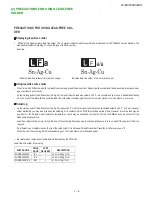
Attaching the stand
• Before attaching (or detaching) the stand, unplug the AC cord from the AC outlet.
• Before performing work spread cushioning over the base area to lay the TV on. This will prevent it from being damaged.
1
Confi rm the screws supplied with the TV.
Screws (
m
10)
2
Insert the support angle into the stand base slot holes. (
1
)
• Please make sure left support angle into the left stand base and right support angle into the right stand base
(left side part engraved “L”, right side part engraved “R”).
3
Push the support angle follow the direction of the arrow mark on the stand base.
Make sure the hook is locked securely and the support angle cannot be pull out.
Push
Push the support angle follow
the direction of the arrow mark
Make sure the hook is locked
securely
4
For easily, user can use polystyrene foam as a jig to hold the stand base when fi xing the screws. (
2
)
2
Example for left side
2
5
Insert the stand into the openings on the bottom of the TV. (
3
)
6
Insert and tighten the screws into the holes on the rear of the TV. (
4
)
Soft cushion
4
5
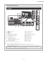
OUTPUT
DC5V 1.5A
HDMI 4
HDMI 5
USB 2
DC5V 0.5A
5
8
AUDIO IN
DIGITAL
AUDIO
OUTPUT
ANALOGUE
RGB (PC)
ARC
8
PC
1
HDMI 1
6
INPUT 6
7
INPUT 7
AUDIO OUT
R - AUDIO - L
R - AUDIO - L
R - AUDIO - L VIDEO/Y PB(CB) PR(CR)
COMPONENT/AV INPUT
VIDEO
RS-232C IOIOI
USB 1
DC5V 1.5A
(DC5V 900mA)
3
AUDIO(L/R)
C.I.
MHL
2
HDMI 2
HDMI 3
OUTPUT
3
4
NOTE
• To detach the stand, perform the steps in reverse order.
• Refer “Building the Work Table” in carton box to assemble the TV.
CAUTION
• Do not attach or detach the stand without holding it.
Doing so can cause the stand to fall, resulting in serious personal injuries as well as damage to the stand.
• The illustrations used throughout this manual are based on LC-60LE360X.
Polystyrene foam
Summary of Contents for Aquos LC-60LE360X
Page 12: ...LC 60 70LE360X 5 2 LC 70LE360X 6 6 6 6 6 6 6 6 6 6 6 6 6 6 6 6 6 6 6 6 6 6 6 6 6 6 6 6 7 ...
Page 34: ...LC 60 70LE360X 8 1 CHAPTER 8 SYSTEM BLOCK DIA GRAM 1 SYSTEM BLOCK DIAGRAM LC 60LE360X ...
Page 35: ...LC 60 70LE360X 8 2 2 SYSTEM BLOCK DIAGRAM LC 70LE360X ...
Page 61: ...LC 60 70LE360X 9 26 ...
Page 72: ...LC 60 70LE360X 11 ...


