LC-60/70LE360X
6 – 3
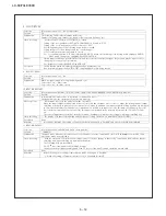
5. SIGNAL ADJUSTMENT
A. PICTURE
ADJUSTMENT
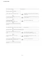
Confirmation of signal from generator (setting to spec level)
PAL
Composite
signal
㸸
0.7Vp-p
s
0.02Vp-p (pedestal to white level)
15K Component signal (50Hz)
㸸
Y level
㸸
0.7Vp-p
s
0.02Vp-p (pedestal to white level)
Pb,
Pr
level
㸸
0.7Vp-p
㸸
0.7Vp-p
s
0.02Vp-p
33K Component signal
㸸
Y level
㸸
0.7Vp-p
s
0.02Vp-p (pedestal to white level)
Pb,
Pr
level
㸸
0.7Vp-p
㸸
0.7Vp-p
s
0.02Vp-Com
a) Adjustment Mode
NO.
E
R
U
D
E
C
O
R
P
N
O
I
T
I
D
N
O
C
M
E
T
I
1
Adjustment Mode
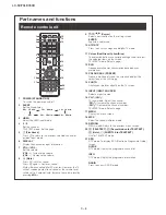
Press the test key at the test remote control
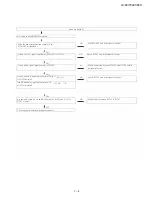
b) Component 15K 50Hz Signal Adjustment (COMP-SD)
NO.
E
R
U
D
E
C
O
R
P
N
O
I
T
I
D
N
O
C
M
E
T
I
1
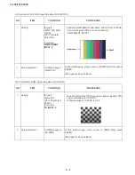
Setting [Signal]
COMP 15K 50Hz
(576i)
100% Full-field
Colour Bar
[Terminal]
COMPONENT
INPUT 6
࣭
Feed the COMPONENT 15K 50Hz (576i) 100% Full-field
Colour Bar signal(100% colour saturation) to
COMPONENT INPUT 3
2
Auto Adjustment
Test Mode page 4
(COMP SD)
At the related page, move cursor to [COMP SD ADJ], press
ENTER.
[OK] appears when finished.
Summary of Contents for Aquos LC-60LE360X
Page 12: ...LC 60 70LE360X 5 2 LC 70LE360X 6 6 6 6 6 6 6 6 6 6 6 6 6 6 6 6 6 6 6 6 6 6 6 6 6 6 6 6 7 ...
Page 34: ...LC 60 70LE360X 8 1 CHAPTER 8 SYSTEM BLOCK DIA GRAM 1 SYSTEM BLOCK DIAGRAM LC 60LE360X ...
Page 35: ...LC 60 70LE360X 8 2 2 SYSTEM BLOCK DIAGRAM LC 70LE360X ...
Page 61: ...LC 60 70LE360X 9 26 ...
Page 72: ...LC 60 70LE360X 11 ...


