background image

80

LC-42SB45U

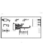
[3]KEY SCHEMATIC DIAGRAM

1

1

2

2

3

3

4

4

5

5

A

A

B

B

C

C

D

D

Menu

CH-

CH+

VOL-

VOL+

----><----|

----><----|

----><----|

POWER

----><----|

----><----|

----><----|

----><----|

----><----|

----><----|

SOURCE

CN016 B1
C016

C1

C017

C1

C018

B2

C019

B3

C020

B4

C021

C3

C022

C4

C023

C2

C024

C1

R016

B2

R017

D3

R018

B3

R019

D4

R020

B4

R021

D2

SW016 A2
SW017 A3
SW018 A4
SW019 C3
SW020 C4
SW021 B5
SW022 C2
TP001 B1
TP002 B1
TP003 B1
TP004 B1

POWER_ON/OFF

KEY_UP_DN_SOURCE

KEY_MENU_L_R

SW022

SW

1

4

3

2

5

TP002

1

SW020

SW

1

4

3

2

5

TP003

1

CN016

63364 4P 2.0mm

1

2

3

4

C023

NC/100N 50V

SW017

SW

1

4

3

2

5

R020
1K8 1/10W

TP004

1

R021
11K 1/10W

SW018

SW

1

4

3

2

5

C024

100N 50V

SW021

SW

1

4

3

2

5

R017
4K3 1/10W

C018

NC/100N 50V

C019

NC/100N 50V

R019
1K8 1/10W

SW019

SW

1

4

3

2

5

C020

NC/100N 50V

C016

100N 50V

C021

NC/100N 50V

C017

100N 50V

C022

NC/100N 50V

R018
4K3 1/10W

SW016

SW

1

4

3

2

5

TP001

1

R016
11K 1/10W

Summary of Contents for AQUOS LC-42SB45U

Page 1: ...N MANUAL 5 3 DIMENSIONS 11 CHAPTER 2 REMOVING OF MAJOR PARTS 1 REMOVING OF MAJOR PARTS 12 CHAPTER 3 ADJUSTMENT PROCEDURE 1 ADJUSTMENT PROCEDURE 17 2 CSM MODE 27 3 FACTORY MODE 28 4 SOFTWARE UPGRADE PRODUCE 28 CHAPTER 4 TROUBLESHOOTING TABLE 1 TROUBLESHOOTING TABLE 33 CHAPTER 5 MAJOR IC INFORMATIONS 1 MAJOR IC INFORMATIONS 40 2 MAJORICINFORMATION 40 3 DETAILICsINFORMATION 49 CONTENTS CHAPTER 6 BLOC...

Page 2: ... or higher sen sitivity or measure the AC voltage drop across the resistor Connect the resistor connection to all exposed metal parts having a return to the chassis antenna metal cabinet screw heads knobs and control shafts escutcheon etc and measure the AC voltage drop across the resistor All checks must be repeated with the AC cord plug connection reversed If necessary a nonpolarized adaptor plu...

Page 3: ...dering As the melting point of lead free solder Sn Ag Cu is about 220 C which is higher than the conventional lead solder by 40 C and as it has poor solder wettability you may be apt to keep the soldering bit in contact with the PWB for extended period of time However Since the land may be peeled off or the maximum heat resistance temperature of parts may be exceeded remove the bit from the PWB as...

Page 4: ...AV in S VIDEO in INPUT 6 HDMI in with HDCP SERVICE Software update OSD language English French Spanish Power requirement AC 120V 60Hz For North America AC 110 240V 50 60Hz For Others Power Consumption 220W 0 7W Standby with AC 120V Weight TV stand 48 72 lbs 22 1 kg TV only 43 8 lbs 19 87 kg Dimension W xH xD TV stand 39 75x27 75x10 75 inch TV only 39 75x27 62x3 88 inch Operating temerature 32 F to...

Page 5: ...l list OSD active jump to that channel in the channel list not tune the channel until OK is pressed Dot key Used for the digital channels ENT Used for accepting the key in channel number VOL Press to adjust the volume CH 1 Press to browse channels 2 Press to turn on TV from stand by mode 3 The channel number should appear on the set FREEZE Frozen the current display SURROUND change audio mode Mono...

Page 6: ...LC 42SB45U 6 TV Front view TV Rear view ...

Page 7: ...screws supplied with the stand unit 2 1 Insert the stand into the openings on the buttom of the TV 2 2Insert and tighten the 4 screws into the 4 holes on the buttom of the TV Note To detach the stand perform the steps in reverse order Detaching the stand neck for Wall mounting 1 1 Loosen the 4 screws that secure the stand neck by using a cross head screwdriver 2 Remove stand neck from the TV set 2...

Page 8: ...batteries have different characteristics 2 Do not mix old and new batteries Mixing old and new batteries can shorten the life of new batteries or cause chemical leakage in old batteries 3 Remove batteries as soon as they are worn out Chemicals that leak from batteries that come in contact with skin can cause a rash If you find any chemical leakage wipe thoroughly with a cloth 4 The batteries suppl...

Page 9: ... contracts according to change in temperature This does not affect the TV s performance Cautions regarding use in high and low temperature environments When the unit is used in a low temperature space e g room office the picture may leave trails or appear slightly delayed This is not a malfunction and the unit will recover when the temperature returns to normal Do not leave the unit in a hot or co...

Page 10: ...rce code for the open source software The source code for the software components whose copyrights are held by SHARP is not distributed acknowledgements The following open source software components are included in this product linuxkernel modutils glibc zlib libpng ...

Page 11: ...2008 03 14 LC 42SB45U 11 3 DIMENSIONS ...

Page 12: ... 1 Assy Panel removal Note Please put your mechine on soft material to avoid to scrape panel when disassembly Front View Fig 1 Back View Fig 2 Step 1 Remove the base assy A Remove 4screws as fig 3 and put out the base Fig 3 B Remove 4 screws as Fig 4 to detach the base stand ...

Page 13: ...2008 03 14 LC 42SB45U 13 Fig 4 Step 2 Remove the Back cover assy Remove 15 screws as Fig 5 Fig 5 Step3 Remove the Power board Remove 5 screws and unplug 3 cables as Fig 6 Fig 6 ...

Page 14: ...4 screws and unplug 6 cables as Fig 7 Fig 7 Step 5 Remove the Speaker L R Remove 4 screws as Fig 8 and Fig 9 Fig 8 Fig 9 Step 6 Remove the IR board Remvoe 1 screws and unplug 1 cable as Fig 10 Fig 10 Step 7 Remove the Key board Unplug 1 cable as Fig 11 ...

Page 15: ...2008 03 14 LC 42SB45U 15 Fig 11 Step 8 Remove the matel frame Remove 16 screws as Fig 12 Fig 12 Step 9 Remvoe the Front cover assy Remove 6 screws as Fig 13 Fig 13 ...

Page 16: ... assemble the whole set execute all processes in reverse order Notes a While re assembling make sure that all cables are placed and connected in their original position b Pay special attention not to damage the EMC foams at the SSB shielding Check that EMC foams are put correctly on their places ...

Page 17: ...NGS Picture Contrast slider 0 100 Brightness slider 0 100 Color slider 0 100 Sharpness slider 0 7 Color temperature Normal Warm Cool Tint slider 7 7 Active contrast Off On View mode Automatic Smart stretch Super zoom Side bar 4 3 Zoom Movie expand 16 9 16 9 subtitle Stretch Wide screen Audio Audio setting slider Audio mode Mono Stereo Virtual surround Alternate audio Main SAP ...

Page 18: ... CC 3 CC 4 T 1 T 2 T 3 T 4 Digital caption service CS 1 CS 2 CS 3 CS 4 CS 5 CS 6 Digital caption options Reset to default Reset to default Size Default Small Standard Large Text Color Default Black White Red Green Blue Yellow Magenta Cyan Opacity Default Solid Transparen Translucen Flashing Background Color Default Black ...

Page 19: ...aised Depressed Outline Left shadow Right shadow Sleep timer slider 0 180 Parental control Channel lock Please enter your PIN US TV ratings lock Please enter your PIN US Movie ratings lock Please enter your PIN Canada English ratings lock Please enter your PIN Canada French ratings lock Please enter your PIN Region ratings lock Please enter your PIN Set PIN Change PIN Please enter your current PIN...

Page 20: ...5 HDMI 2 INPUT 6 HDMI 3 INPUT 7 PC Clock Enter Time Hrs Mins AM PM Favorite channels Only in TV A Select channel B Select channel C Select channel D Select channel All data clear Start now Current software info Current software Version Reset Start now z PC OSD Menu Layer1 Layer2 Layer3 Layer4 Layer5 SETTINGS Picture Contrast slider 0 100 Brightness slider 0 100 Color temperature Normal ...

Page 21: ...dio setting slider Surround Off On Setup Language English Francais Espanol Input source TV INPUT 1 AV1 INPUT 2 AV2 INPUT 3 Side AV INPUT 4 HDMI 1 INPUT 5 HDMI 2 INPUT 6 HDMI 3 INPUT 7 PC Picture Adjustment Auto adjust Start Manual adjust Phase Clock Horizontal Vertical Reset Start now ...

Page 22: ...AIN_B and ADC_OFFSET_R ADC_OFFSET_G ADC_OFFSET_B Then store those values to NVM 2 Apply Flat80 pattern 80 white pattern 3 Set color temperature to NORMAL 4 At FAC mode menu adjust the CLR TEMP R CLR TEMP G CLR TEMP B values to meet NORMAL color coordinates specification below Then store those values to NVM 3 Set color temperature to COOL 4 At FAC mode menu adjust the CLR TEMP R CLR TEMP G CLR TEMP...

Page 23: ..._OFFSET_R ADC_OFFSET_G ADC_OFFSET_B Then store those values to NVM 2 Apply Flat_73 pattern or 75IRE pattern 3 Set color temperature to NORMAL 3 Copy CLR_TEMP_R CLR_TEMP_G and CLR_TEMP_B values from NORMAL color temperature in Analog TV mode Check whether x y color coordinates meet NORMAL color specification below If color coordinates are out of specification fine tune CLR_TEMP_R CLR_TEMP_G and CLR...

Page 24: ... loaded 3 2 Use DVD player Pioneer DVD player xxx or equivalent DVD player with HDMI output to verify HDCP key loaded in the set The video should be smoothly displayed when HDCP key is correctly loaded 4 Preset NVM data NVM U301 data has to be preset data according following table NVM file name description 1 FL4 project name 2 CMO 42 Panel type and size 3 NVM_xxxx finalize testing Date 4 xxxx chec...

Page 25: ...ting a Picture part Picture Format Widescreen Color Temp in Factory mode Cool b Sound part default SOUND VOLUME 20 Sound mode Stereo Alternative audio Main AVL off Smart Picture VIDEO_PWM_NORMAL 15 VIDEO_PWM_MEDIUM 120 VGA_PWM_MIN 200 VGA_PWM_MAX 15 Standard Personal Stereo AVL off EQ BAND1 120Hz 0 EQ BAND2 500Hz 0 EQ BAND3 1 5KHz 0 EQ BAND4 5KHz 2 EQ BAND5 10KHz 2 Sports Stereo AVL off EQ BAND1 1...

Page 26: ...c contrast Picture format wide Sports Contrast 70 Brightness 45 Color 65 Sharpness 5 Color temperature normal Tint 0 Dynamic contrast Picture format wide Standard Contrast 50 Brightness 50 Color 50 Sharpness 4 Color temperature normal Tint 0 Dynamic contrast Picture format wide Movie Contrast 58 Brightness 50 Color 50 Sharpness 5 Color temperature normal Tint 0 Dynamic contrast on Picture format w...

Page 27: ... retrieved out of production data 2 Production code 14 digit production cde to be retrieced per set to be written in NVM EEPROm 3 SW naming main processor SW naming of MSTAR Trident see format in generic service document 4 SW naming extra processor if valid 5 Code 1 Logging I2C errcodes in NVM EEPROM 5 last logged errors 6 Code 2 Logging I2C errcodes in NVM EEPROM 5 last logged errors 7 Key HDCP H...

Page 28: ...l to the Factory selection and press then choose start now and press ENTER key to enter the factory model Start now 3 In the factory setting press and key to set the state that you want 4 Press Menu to exit or select 0 in the menu selection by up down key then press enter Note How to reset the factory setting 1 Enter the facotry model see page 28 then choose item 8 VIRGIN_MODE ...

Page 29: ...29 2 Change the state from Off to On By pressing key 3 Press Menu to exit or select 0 in the menu selection by up down key then press enter 4 Turn Power Off Then power on the set you can find the factory settings has been OK ...

Page 30: ... the environment first This chapter lists the setup requirements and guides you to setup and test your development environment Connect to ISP Board Use USB port connecting PC MT537x Board via ISP board Code number 715G537XL2 To PC USB port To system board service port ISP tool ISP tool 1 Unzip USB2COM Driver zip to C ...

Page 31: ...in or F4_image bin 3 Make sure the Type MTK538X USB Baud Rate 115200 Load the correct bin file Load bin file on the Linux system or on the local Windows file system Ex SHARP_ATSC_DLH_V0_34A_080714 bin Set Bridge Auto Set Flash BaudRate 4 Set COM port resource that used by USB Port PL 2303 Driver Installer zip PL 2303 Driver Installer zip ...

Page 32: ...LC 42SB45U 32 5 Set Baud rate 115200 High speed item Enable MT538x 6 Push Upgrade button Waiting for Finished message Press 確定 button 7 Mainboard Power Off On ...

Page 33: ...ction circuit etc is checked NO Is a voltage of 5V applied to pin 11 12 of connector CN902 Set the main power SW to OFF Does the switching circuit operate normally Check circuit around the primary side T904 IC903 Q922 Q924 ZD911 D924 D908 ZD910 etc the secondary side D927 L907 etc the AC_DET circuit ZD912 ZD913 IC911 IC913 Q918 IC909 Q915 etc and the protection circuit NO Are 24V output as for the...

Page 34: ...n P26 of IC U400 NO Check the tuner and its peripheral circuits Replace as required NO Check IC U400 its peripheral circuits Refer to No sound output in all modes Is the DIF signal output from pin 18 and pin 19 of TUNER TU201 NO Check the tuner and its peripheral circuits Replace as required Refer to No sound output in all modes Is the audio signal properly sent to pin 2 AV1_AudioLIN and pin 4 AV1...

Page 35: ...nal input device Refer to No sound output in all modes Is the audio signal properly sent to pin K23 AV3_LIN and pin K24 AV3_RIN of IC U400 NO Check the line between CN650 and IC U400 Is the audio signal properly sent to pin 2 VGA_AudioLIN and pin 3 VGA_AudioRIN of CN555 NO Check the connection to CN555 and the external input device Refer to No sound output in all modes Is the audio signal properly...

Page 36: ...nal output from 1st_channel and 2nd_channel of IC U400 in each mode A0N A0P A1N A1P A2N A2P A3N A3P CLK1N CLK1P A4N A4P A5N A5P A6N A6P A7N A7P CLK2N CLK2P Check IC U400 and its peripheral control circuits Is picture signal input from pin 4 of TUNER TU201 to pin AC26 of IC U400 Is TUNER_CVBS signal output from pin 4 of TUNER TU201 NO Check whether I2C is normally accessed between TU201 and IC U400...

Page 37: ...nal input device that connects of CN650 Refer to The picture doesn t appear in all modes Is CVBS signal sent to pin AD26 of IC U400 NO Check the line between IC U400 and CN650 Is Y C signal sent to pin 8 Y 7 C of AV3 CN650 NO Check the setting of an external input device that connects of CN650 Is Y C signal sent to pin AD25 Y AE26 C of IC U400 NO Check the line between IC U400 and CN650 NO Is Comp...

Page 38: ...08 EEPROM pin 5 SDA accessed and is it read from pin 15 pin 16 of a HDMI terminal CN702 NO Is access possible in the re writing or exchange of EDID data of IC U708 Check CN702 IC U708 and peripheral circuits Is TMDS signal input into pin AF7 AE7 RX2 AF6 AE6 RX1 AF5 AE5 RX0 AF4 AE4 RXC of IC U400 Check the line between IC U400 and CN702 NO Is the HOT_PLUG detection function of pin 19 of a HDMI term...

Page 39: ... EDID data pin 6 SCL of IC U700 EEPROM pin 5 SDA accessed and is it read from pin 15 16 of a HDMI terminal CN701 NO Is access possible in the re writing or exchange of EDID data of IC U700 Check CN701 IC U700 and peripheral circuits Is TMDS signal input into pin AF15 AE15 RX2 AF14 AE14 RX1 AF13 AE13 RX0 AF12 AE12 RXC of IC U400 Check the line between IC U400 and CN701 NO Is R G B H V signal sent t...

Page 40: ...he device outputs the demodulated data as a standard MPEG 2 transport stream in within parallel or serial format It also support free QAM with cable system The MT5382 platform support different source AV1 AV2 support two YPbPr component inputs they can support SD HD format Side AV support CVBS YC signal share with same audio HDMI support HDMI DVI input the DVI audio share with side AV connector Al...

Page 41: ... micro processor for stream process and MPEG start code detection MPEG2 JPEG Decoder Supports one MPEG 2 HD decoder MPEG MP ML MP HL and MPEG 1 video standards The MT5382AR supports de blocking filter The MT5382AR supports JPEG decode base line JPEG file 2D Graphics Supports multiple color modes Point horizontal vertical line primitive drawings Rectangle fill and gradient fill functions Bitblt wit...

Page 42: ...mb filter Built in motion adaptive 3D Noise Reduction VBI data slicer for CC TT decoding Supports 2 S Video The MT5382AR supports 4 channel CVBS Supports SCART connector VGA In Supports VGA input up to UXGA 162 MHz Supports full VESA standards Component Video In Supports two component video inputs Supports 480i 480p 576i 576p 720p 1080i 1080p Audio line in interface The MT5382AR supports 1 bit lin...

Page 43: ...y only a single SAW is required Dual digital AGC controls for IF and RF respectively Full digital frequency offset recovery with wide acquisition range 1 MHz for ATSC and 250 kHz for CATV reception EIA CEA 909 antenna interface both mode A and mode B are supported Analog TV IF Demodulator Supports NTSC M N standard Accepts IF frequency at 45 75 MHz Full digital AGC control and carrier recovery Per...

Page 44: ...nge from 2 9V to 18V while the output voltage can be set starting from 0 6V to VIN Having a minimum input voltage of 2 9V the device is suitable for buses staring from for 3 3V bus Requiring a minimum set of external components the device includes an internal 250KHz switching frequency oscillator that can be externally adjusted up to 1MHz The QFN package with exposed pad allows reducing the RthJA ...

Page 45: ... stereo half bridge configuration SE Features Operating voltage from 10 V to 36 V asymmetrical or 5 V to 18 V symmetrical Mono bridged tied load full bridge or stereo single ended half bridge application Application without heatsink using thermally enhanced small outline package High efficiency and low power dissipation Thermally protected and thermal foldback Current limiting to avoid audio holes...

Page 46: ...s which allows low quiescent current operation independently of output load current Features 0 8A Guaranteed output current Ultra low dropout voltage 150mV typ 0 8A load 20mV typ 150mA load Very low quiescent current 1mA typ 0 8A load 1µA max 25 C in off mode Logic controlled electronic shutdown Current and thermal internal limit 1 5 Output voltage tolerance 25 C Fixed and ADJ output voltages 1 22...

Page 47: ... two I O read mode 50MHz 15pF TTL Load which is equivalent to 100MHz Fast program time 1 4ms typ and 5ms max page 256 byte per page Byte program time 7us typical Continuously program mode automatically increase address under word program mode Fast erase time 60ms typ sector 4K byte per sector 0 7s typ block 64K byte per block 25s typ for 32Mb Low Power Consumption Low active read current 25mA max ...

Page 48: ...S SCLK Input Serial clock input SI Input Serial Data Input SO Output Serial Data Output WP ACC pin Hardware write protection and program erase acceleration HOLD pin pause the chip without diselecting the chip PACKAGE 16 pin SOP 300mil 8 land WSON 8x6mm or6x5mm 8 pin SOP 200mil 150mil 8 pin PDIP 300mil All Pb free devices are RoHS Compliant ...

Page 49: ...2008 03 14 LC 42SB45U 49 3 Detailed ICs Information 3 1 U400 MT5382 AR 3 1 1 Block Diagram 3 1 2 Pin Connections and short description ...

Page 50: ...LC 42SB45U 50 3 2 U102 LP2996MRX PSOP 8 3 2 1 Pin Connections and short description ...

Page 51: ... frequency compensation 5 FB Feedback input Connecting the output voltage directly to this pin the output voltage is regulated at 0 6V To have higher regulated voltages an external resistor divider is required from Vout to FB pin 6 FSW The switching frequency can be increased connecting an external resistor from FSW pin and ground If this pin is left floating the deice works at its free running fr...

Page 52: ... Driver Power Supply J1 VDDL PWR Power Supply E1 J9 M9 R1 VDD PWR Power Supply E7 F2 F8 H2 H8 VSSQ PWR I O Driver Power Supply J7 VSSDL PWR Power Supply A3 3 J3 N1 P9 VSS PWR Power Supply Not Connected 16 Organization A2 E2 L1 R3 R7 R8 NC NC Not Connected Other Pins 16 Organization K9 ODT I SSTL On Die Termination Control 3 5 U600 TDA8932B 3 5 1 Block diagram 3 5 1 Pin Connections and short descri...

Page 53: ...2008 03 14 LC 42SB45U 53 3 6 U151 LD1117DT33TR 3 6 1 Block Diagram 3 7 U721 LD39080PT 3 7 1 Block Diagram 3 7 2 Pin Connections and short description ...

Page 54: ...LC 42SB45U 54 3 8 U402 MX25L3205DMI 12G SOP 16 3 8 1 Block Diagram ...

Page 55: ...2008 03 14 LC 42SB45U 55 3 8 2 PIN CONFIGURATION ...

Page 56: ...LC 42SB45U 56 CHAPTER 6 BLOCK DIAGRAM WIRING DIAGRAM 1 MT5382 POWER MAGAGEMENT BLOCK DIAGRAM ...

Page 57: ...2008 03 14 LC 42SB45U 57 2 MAIN BOARD BLOCK DIAGRAM ...

Page 58: ...LC 42SB45U 58 3 WIRING DIAGRAM ...

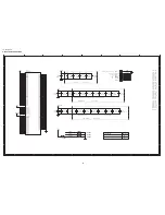
Page 59: ...LC 42SB45U CHAPTER 7 PRINTED WIRING BOARD 1 MAIN UNIT PRINTED WIRING BOARD MAIN Unit Side A 59 ...

Page 60: ...60 LC 42SB45U MAIN Unit Side B ...

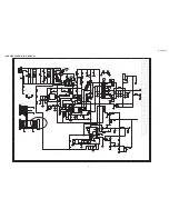
Page 61: ...LC 42SB45U 1 POWER UNIT PRINTED WIRING BOARD POWER Unit Side A 61 ...

Page 62: ...LC 42SB45U POWER Unit Side B 62 ...

Page 63: ...LC 42SB45U 63 3 KEY BOARD UNIT PRINTED WIRING BOARD KEY BOARD Unit Side A KEY BOARD Unit Side A ...

Page 64: ...64 LC 42SB45U IR Unit Side A 3 IR UNIT PRINTED WIRING BOARD IR Unit Side A Cn001 A2 ...

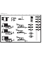
Page 65: ...B 5 5V_SW 2 8 10 11 12 13 14 5V_STB 2 7 8 9 5V1_TUN 2 VTT 6 MEM_VREF 6 DV33 2 4 5 7 14 3V3SB 2 9 CEC_PWR 9 DV33SB 5 7 9 12 13 12V 5V_STB 5V_SW 5V_STB 12V DV11 12V DV18_DDR 5V1_TUN 5V_TunerB VTT DV18_DDR 24V DV18_DDR 24V DV33 3V3SB DV33SB STB_PWR5V DV33SB 5V_SW STB_PWR5V 5V_STB 5V_TunerB 5V_STB R118 NC 0R05 1 10W 5 C121 NC 100N 16V U103 L5985 1 2 3 4 5 6 7 8 9 Vout SYNC INH COMP FB FSW GND Vcc TH1 ...

Page 66: ...GND 1 3 4 5 6 7 8 9 10 11 12 13 14 AV12 8 10 12 PANEL_VCC 14 AV33 8 12 13 14 AV25 3 11 5V1_TUN 1 24V 1 13 3V3SB 1 9 5V_SW DV33 AV33 3V3SB 5V_STB 5V_SW 5V1_TUN 5V_TUNER PANEL_VCC 12V PANEL5V PANEL_VCC PANEL5V 24V 12V AV25 AV12 5V_SW AV25 5V1_TUN 5V_TUNER C162 100uF 16V C152 1000uF 16V ADJ U154 LD1117DTTR 3 1 2 VIN GND VOUT C178 47uF 25V ADJ U151 LD1117DT33TR 3 1 2 VIN GND VOUT C167 47uF 25V L150 NC...

Page 67: ..._IF GND 1 2 4 5 6 7 8 9 10 11 12 13 14 5V_TUNER 2 FAT_IN2 11 FAT_IN2 11 CVBS0T 11 ADIN3 5 AV25 2 11 5V_TUNER 5V_TUNER AV25 5V_TUNER R209 4K7 1 10W R200 0R05 1 10W 5 C209 33P 50V TP205 1 TU201 TDQU4 507A 20 21 22 23 1 2 3 4 5 6 7 8 9 10 11 12 13 14 15 16 17 18 19 TH1 TH2 TH3 TH4 NC or OOB B1_ 5V GND or SIF O P GND or CVBS RF_AGC Mon NC or AFT NC or IF_AGC Mon NC or B2_Ana_ 5V TU_ 32V GND GND SCL SD...

Page 68: ...N12 P12 T12 K13 U13 L14 T14 L15 T15 K16 U16 L17 N17 P17 T17 K18 M18 AB4 AA5 F23 E24 D24 F10 F11 E1 AB1 T4 Y4 F5 L5 R5 W5 H6 K6 L11 N11 P11 T11 K12 M12 R12 U12 L13 M13 N13 P13 R13 T13 K14 M14 N14 P14 R14 U14 K15 M15 N15 P15 R15 U15 L16 M16 N16 P16 R16 T16 K17 M17 R17 U17 L18 H1 W1 B2 C3 D4 M4 V4 E5 J5 N5 U5 F6 N18 P18 T18 H5 E6 D5 C4 B3 A2 E21 E22 E25 D26 R18 U18 C7 VCCK VCCK VCCK VCCK VCCK VCCK VC...

Page 69: ...INVERTER_SW 14 SOUND_EN 13 LED_W 7 DC_SWITCH 7 9 PANEL_VCC_ON OFF 2 STAND_BY 1 OPWRSB 1 HPD0 12 HPD1 12 ADIN3 3 MUTE 13 KEY_MENU_L_R 7 OPWM2 4 EDID_WEN 10 12 KEY_UP_DN 7 9 LED_R 7 3V3SB 1 2 9 MAIN_SCL 9 MAIN_SDA 9 CEC_INT 9 DV33SB DV33 DV33 DV33 DV33SB DV33 DV33SB DV33SB DV33 DV33 DV33SB DV33SB DV33SB DV33SB DV33SB DV33SB DV33SB DV33SB DV33 DV33SB DV33SB U400B MT5382AR D12 C12 C20 D19 A21 B20 Y5 A...

Page 70: ...J1 J2 J3 J7 J8 J9 K2 K3 K7 K8 K9 L1 L2 L3 L7 L8 M2 M3 M7 M8 M9 N1 N2 N3 N7 N8 P2 P3 P7 P8 P9 R1 R2 R3 R7 R8 G3 VDD NC VSS VSSQ UDQS VDDQ DQ14 VSSQ UDM UDQS VSSQ DQ15 VDDQ DQ9 VDDQ VDDQ DQ8 VDDQ DQ12 VSSQ DQ11 DQ10 VSSQ DQ13 VDD NC VSS VSSQ LDQS VDDQ DQ6 VSSQ LDM LDQS VSSQ DQ7 VDDQ DQ1 VDDQ DQ0 VDDQ DQ4 VSSQ DQ3 DQ2 VSSQ DQ5 VDDL VREF VSS VSSDL CK VDD CKE WE RAS CK ODT NC BA2 BA0 BA1 CAS CS A10 AP ...

Page 71: ...SWITCH 5 9 KEY_UP_DN 5 9 LED_W 9 RC6 8 9 LED_R 9 U0RX 9 U0TX 9 RXD_CEC 9 TXD_CEC 9 DV33SB DV33SB DV33SB 5V_STB DV33 DV33 DV33 DV33SB DV33SB DV33SB DV33SB CN401 63384 4P 2 0MM 1 2 3 4 R431 33R 1 16W 5 TP407 1 TP414 1 R407 NC 4K7 1 10W TP416 1 TP400 1 R420 10K 1 16W 5 R404 100R 1 10W R419 10K 1 16W 5 R412 NC 4K7 1 10W TP408 1 C413 100N 50V R430 33R 1 16W 5 R437 0R05 1 10W ACC U402 MX25L3205DMI 12G 1...

Page 72: ... 14 5V_SW 1 2 10 11 12 13 14 AV12 2 10 12 GND 1 2 3 4 5 6 7 9 10 11 12 13 14 RC6 7 9 5V_STB 1 2 7 9 AV33 AV12 5V_SW 5V_SW 5V_SW 5V_STB 5V_STB R454 NC 0R05 1 16W TP451 1 C453 100N 16V C452 4UF7 10V CN451 NC 64835 5P 2 5mm 1 2 3 4 5 TP452 1 C450 100uF 16V R451 0R05 1 16W U400D MT5382AR AF2 AD3 AE3 AF3 AB5 AC4 AD4 R25 T26 T25 U26 P24 P22 R26 R22 R24 T22 T24 T23 R23 USB_VRT AVSS33_USB USB_DM USB_DP AV...

Page 73: ...Power_UP 13 U0RX 7 U0TX 7 TXD_CEC 7 RXD_CEC 7 3V3SB 3V3SB 3V3SB 3V3SB 3V3SB 3V3SB 5V_STB DV33SB DV33SB 3V3SB DV33SB DV33SB DV33SB 3V3SB DV33SB DV33SB DV33SB Q505 NC 2N7002 R516 33R 1 16W 5 R513 NC 4K7 1 16W 5 R548 33R 1 16W 5 R542 4K7 1 16W 5 R540 NC 0R05 1 16W R521 33R 1 16W 5 C508 NC 100N 16V R518 33R 1 16W 5 FB500 NC 220R 400mA 1 2 R523 33R 1 16W 5 R538 0R05 1 16W R514 NC 4K7 1 16W 5 R507 NC 33...

Page 74: ... BLU PB0_IN GRN_GND GRN_GND VGASDA_IN VGA_HIN VGA_VIN VGASCL_IN BLU GRN RED AV1_RIN 13 AV1_LIN 13 AV2_RIN 13 AV2_LIN 13 AV12 2 8 12 5V_SW 1 2 8 11 12 13 14 VGA_RIN 13 VGA_LIN 13 EDID_WEN 5 12 SPDIF_OUT 11 VGA_HIN 9 VGA_VIN 9 GND 1 2 3 4 5 6 7 8 9 11 12 13 14 5V_SW 5V_SW 5V_SW 5V_SW 5V_SW 5V_SW 5V_SW VGA_PLUGPWR 5V_SW 5V_SW 5V_SW 5V_SW 5V_SW 5V_SW 5V_SW 5V_SW 5V_SW 5V_SW VGA_PLUGPWR 5V_SW 5V_SW 5V_...

Page 75: ...V3_LIN 5V_SW AV3_AudioRIN AV3_AudioLIN AV3_SY_IN AV3_SC_IN ASPDIF AV3_SC_IN AV3_SY_IN AV3_CVBS_IN AV3_AudioLIN AV3_AudioRIN SPDIF_OUT SPDIF_OUT FAT_IN2 3 AV3_RIN 13 CVBS0T 3 FAT_IN2 3 AV25 2 3 GND 1 2 3 4 5 6 7 8 9 10 12 13 14 AV3_LIN 13 5V_SW 1 2 8 10 12 13 14 ASPDIF 13 SPDIF_OUT 10 AV25 AV25 AV25 AV25 5V_SW 5V_SW 5V_SW 5V_SW 5V_SW 5V_SW R653 NC 75R 1 16W 5 C657 100N 16V C668 4 7UF 10V L655 0U10 ...

Page 76: ...ET TH3 TH4 TH5 C714 100N 16V C717 100N 16V Q707 2SK1828 CN702 CON HDMI V 19P 20 21 1 2 3 4 5 6 7 8 9 10 11 12 13 14 15 16 17 18 19 22 23 24 TH1 TH2 D2 D2 Shield D2 D1 D1 Shield D1 D0 D0 Shield D0 CK CK Shield CK CE Remote NC DDC CLK DDC DATA GND 5V HP DET TH3 TH4 TH5 R741 47K 1 16W 5 U710 RClamp0524P TCT 1 2 3 4 5 6 7 8 9 10 IN1 IN2 GND IN3 IN4 OUT4 OUT3 GND OUT2 OUT1 L700 0U10 H R738 1K 1 16W 5 R...

Page 77: ... 9 DV33SB 1 5 7 9 12 5V_SW 12V AV33 AV33 AV33 AV33 AV33 DV33SB R625 10R 1 4W 1206 R608 10K 1 10W 5 C614 100uF 10V C621 470N 16V X7R 10 R632 10R 1 4W FB603 120R 500mA 1 2 R634 20K 1 16W 5 C638 15N 50V C608 100N 16V R630 NC 10K 1 16W 5 R641 12K1 10W Q605 BC857BW 1 2 3 R600 0R05 1 16W 5 C603 1uF 16V C640 470N 50V CN604 63382 2P 2 0MM 1 2 R635 39K 1 16W 5 C633 15N 50V C690 10N 50V C630 680uF 25V C624 ...

Page 78: ...LL AVDD33_VPLL AVDD33_VPLL AV33 A0P A0N A1P A1N A2P A2N CK1P CK1N A3N INVERTER_ON_OFF DV33 1 2 4 5 7 5V_SW 1 2 8 10 11 12 13 OPWM1 5 INVERTER_ON_OFF 1 BRIGHT_ADJ 1 INVERTER_SW 5 GND 1 2 3 4 5 6 7 8 9 10 11 12 13 PANEL_VCC 2 AV33 2 8 12 13 DV33 5V_SW 5V_SW DV33 DV33 DV33 DV33 DV33 PANEL_VCC AV33 AV33 C757 1uF 16V R755 NC 4K7 1 10W C750 100N 16V C759 NC 10U 16V TP766 1 C753 1uF 16V R761 4K7 1 10W Q7...

Page 79: ... RV904 TVR14511KFC4FY IC914 TL431ACZ AP 1 3 2 R917 12K 1 6W R920 10K 1 6W R945 1 0KΩ 1 C907 180uF 450V FB920 35R W5RH2 5X3X1 0 1 2 C922 100N 50V R973 680R 1 8W R936 100KΩ C932 10N 25V HD901 HEATSINK HQ902 HEATSINK ZD914 BZX84 B18 1 3 R966 2K2 1 8W CN902 64842 12P 2 5MM 1 2 3 4 5 6 7 8 9 10 11 12 R977 2M2 1 4W R978 120K 1 8W R987 100K 1 6W C934 47uF 25V IC909 TCET1103G 1 2 4 3 R941 18K 1 8W C969 33...

Page 80: ...01 B1 TP002 B1 TP003 B1 TP004 B1 POWER_ON OFF KEY_UP_DN_SOURCE KEY_MENU_L_R SW022 SW 1 4 3 2 5 TP002 1 SW020 SW 1 4 3 2 5 TP003 1 CN016 63364 4P 2 0mm 1 2 3 4 C023 NC 100N 50V SW017 SW 1 4 3 2 5 R020 1K8 1 10W TP004 1 R021 11K 1 10W SW018 SW 1 4 3 2 5 C024 100N 50V SW021 SW 1 4 3 2 5 R017 4K3 1 10W C018 NC 100N 50V C019 NC 100N 50V R019 1K8 1 10W SW019 SW 1 4 3 2 5 C020 NC 100N 50V C016 100N 50V C...

Page 81: ...3 B2 TP004 B2 TP005 B2 U001 C4 LED_G LED_R 5V_STB RC6 5V_STB 5V_STB 5V_STB R006 2 2KOHM 5 1 10W TP004 1 R002 470 OHM 5 1 10W C002 10N 50V C004 100N 50V C003 NC 10N 50V TP001 1 LED001 KPB 3025SURKPBAC 1 3 2 4 TP003 1 R004 2 2KOHM 5 1 10W U001 IRM 3638TF41 3 1 2 VS OUT GND Q001 BC847C CN001 63385 5P 2 0MM 1 2 3 4 5 R008 100 OHM 5 1 10W R007 2 7KOHM 5 1 10W TP005 1 Q002 BC847C TP002 1 R001 510 OHM 5 ...

Page 82: ...0002 0 01 FOB screws base 100 9JR0100000009 0 01 FOB screws base PACKING PARTS 143 9JR4500000003 0 01 FOB P E BAG 100 X 70 9JR7050000010 2 55 FOB CUSHION ASSY 455 9JR4500000002 0 39 FOB P E BAG 450 9JR4400000009 3 31 FOB CARTON MISCELLANEA 101 9JR0100000007 0 01 FOB SCREW 102 9JR0100000001 0 01 FOB SCREW 103 9JR0100000003 0 01 FOB SCREW 4 6MM 104 9JR0100000004 0 01 FOB SCREW 105 9JR0100000010 0 01...

Page 83: ...0000036 0 01 FOB CAP CHIP 0603 0 1UF K 16V X7R C124 9JR6500000014 0 01 FOB CAP CHIP 0402 100N 16V X7R 10 C125 9JR6500000036 0 01 FOB CAP CHIP 0603 0 1UF K 16V X7R C126 9JR6500000036 0 01 FOB CAP CHIP 0603 0 1UF K 16V X7R C127 9JR6500000096 0 01 FOB CAP CHIP 4U7 10V Y5V 20 80 C127 9JR6500000097 0 01 FOB CAP CHIP 4 7UF 10V Y5V 20 80 C128 9JR6500000051 0 01 FOB CAP CHIP 0603 330PF J 50V NPO C129 9JR6...

Page 84: ...0603 10NF K 50V X7R C205 9JR6500000077 0 01 FOB CAP CHIP 0805 10UF Z 10V Y5V C206 9JR6500000036 0 01 FOB CAP CHIP 0603 0 1UF K 16V X7R C207 9JR6500000011 0 01 FOB CAP CHIP 0402 10N 16V X7R 10 C208 9JR6500000011 0 01 FOB CAP CHIP 0402 10N 16V X7R 10 C209 9JR6500000020 0 01 FOB CAP CHIP 0402 33P 50V NPO 5 C209 9JR6500000021 0 01 FOB CAP CHIP 0402 33P 50V NPO 5 C210 9JR6500000036 0 01 FOB CAP CHIP 06...

Page 85: ... 16V X7R C310 9JR6500000044 0 01 FOB CAP CHIP 0603 1UF K 16V X7R C311 9JR6500000043 0 01 FOB MLCC 0603 CAP 1uF K 16V X7R C311 9JR6500000044 0 01 FOB CAP CHIP 0603 1UF K 16V X7R C312 9JR6700000022 0 01 FOB EC 220uF 16V KM 8x12mm C318 9JR6500000014 0 01 FOB CAP CHIP 0402 100N 16V X7R 10 C319 9JR6500000092 0 01 FOB CAP CHIP 4 7UF 10V X7R 10 C350 9JR6700000018 0 01 FOB EC 100uF 16V KM 6 3x11mm C350 9J...

Page 86: ... Z 50V Y5V C413 9JR6500000037 0 01 FOB CAP CHIP 0603 100N 50V Y5V 20 80 C413 9JR6500000038 0 01 FOB CAP CHIP 0603 0 1UF Z 50V Y5V C414 9JR6500000037 0 01 FOB CAP CHIP 0603 100N 50V Y5V 20 80 C414 9JR6500000038 0 01 FOB CAP CHIP 0603 0 1UF Z 50V Y5V C450 9JR6700000011 0 01 FOB EC 100uF 16V RGA 6 3x11mm C451 9JR6500000043 0 01 FOB MLCC 0603 CAP 1uF K 16V X7R C451 9JR6500000044 0 01 FOB CAP CHIP 0603...

Page 87: ...C581 9JR6500000077 0 01 FOB CAP CHIP 0805 10UF Z 10V Y5V C582 9JR6500000077 0 01 FOB CAP CHIP 0805 10UF Z 10V Y5V C585 9JR6500000018 0 01 FOB CAP CHIP 0402 22P 50V NPO 5 C585 9JR6500000019 0 01 FOB CAP CHIP 0402 22P 50V NPO 5 C586 9JR6500000006 0 01 FOB CAP CHIP 0402 100P 50V NPO 5 C586 9JR6500000007 0 01 FOB CAP CHIP 0402 100P 50V NPO 5 C587 9JR6500000011 0 01 FOB CAP CHIP 0402 10N 16V X7R 10 C58...

Page 88: ...628 9JR6500000037 0 01 FOB CAP CHIP 0603 100N 50V Y5V 20 80 C628 9JR6500000038 0 01 FOB CAP CHIP 0603 0 1UF Z 50V Y5V C629 9JR6500000037 0 01 FOB CAP CHIP 0603 100N 50V Y5V 20 80 C629 9JR6500000038 0 01 FOB CAP CHIP 0603 0 1UF Z 50V Y5V C630 9JR6700000032 0 04 FOB EC 680uF 25V RGA 10x16mm C631 9JR6500000088 0 01 FOB CAP CHIP 0805 470N 16V X7R 10 C631 9JR6500000089 0 01 FOB CAP CHIP 0805 470N 16V X...

Page 89: ...0V NPO C666 9JR6500000046 0 01 FOB CAP CHIP 0603 1U 10V Y5V 20 80 C667 9JR6500000043 0 01 FOB MLCC 0603 CAP 1uF K 16V X7R C667 9JR6500000044 0 01 FOB CAP CHIP 0603 1UF K 16V X7R C668 9JR6500000092 0 01 FOB CAP CHIP 4 7UF 10V X7R 10 C669 9JR6500000014 0 01 FOB CAP CHIP 0402 100N 16V X7R 10 C670 9JR6500000043 0 01 FOB MLCC 0603 CAP 1uF K 16V X7R C670 9JR6500000044 0 01 FOB CAP CHIP 0603 1UF K 16V X7...

Page 90: ... 0603 1U 10V Y5V 20 80 CN100 9JR3300000005 0 05 FOB WAFER 2 0MM 12P 63392 CN401 9JR3300000003 0 01 FOB WAFER 2 0MM 4P 63384 CN402 9JR3300000004 0 03 FOB WAFER 2 0MM 7P 63387 CN403 9JR3300000006 0 06 FOB WAFER 2 0MM 3P 63043 CN450 9JR8800000015 0 14 FOB USB CONNECTOR A TYPE 5409 03 300 71 CN550 9JR8800000007 0 12 FOB RCA JACK 1 2 W R V A MKC21 092AN P CN550 9JR8800000008 0 11 FOB RCA JACK 1 2 W R V...

Page 91: ...0C D706 9JR9300000001 0 01 FOB LL4148 GSO8 D706 9JR9300000029 0 01 FOB BAS32L SOD80C D707 9JR9300000030 0 01 FOB DIODE BAS316 SOT 323 PHILIPS D708 9JR9300000001 0 01 FOB LL4148 GSO8 D708 9JR9300000029 0 01 FOB BAS32L SOD80C D709 9JR9300000001 0 01 FOB LL4148 GSO8 D709 9JR9300000029 0 01 FOB BAS32L SOD80C FB100 9JR7100000010 0 01 FOB CHIP BEAD 220R 3000mA MPZ2012S221A FB101 9JR7100000010 0 01 FOB C...

Page 92: ... 9JR7100000011 0 01 FOB CHIP BEAD 600R 200mA FCM1608K 601T02 FB651 9JR7100000014 0 01 FOB CHIP BEAD 600R 500mA MMZ1608S601CT FB700 9JR7100000011 0 01 FOB CHIP BEAD 600R 200mA FCM1608K 601T02 FB700 9JR7100000014 0 01 FOB CHIP BEAD 600R 500mA MMZ1608S601CT FB701 9JR7100000011 0 01 FOB CHIP BEAD 600R 200mA FCM1608K 601T02 FB701 9JR7100000014 0 01 FOB CHIP BEAD 600R 500mA MMZ1608S601CT FB702 9JR710000...

Page 93: ...R10K L701 9JR7300000002 0 01 FOB CHIP INDUCTOR 0U10 10 FCI1608F R10K Q100 9JR5700000005 0 01 FOB BC847C Q100 9JR5700000010 0 01 FOB TRA BC847C 100mA 50V SOT 23 Q101 9JR5700000005 0 01 FOB BC847C Q101 9JR5700000010 0 01 FOB TRA BC847C 100mA 50V SOT 23 Q103 9JR5700000020 0 17 FOB FET SI3441BDV TSOP 6 Q104 9JR5700000019 0 14 FOB SI5441DC 1206 8 Q106 9JR5700000005 0 01 FOB BC847C Q106 9JR5700000010 0 ...

Page 94: ...R5700000041 0 01 FOB RST CHIP 1K 1 16W 5 R127 9JR5700000071 0 01 FOB RST CHIP 10K 1 10W 5 R127 9JR5700000072 0 01 FOB RST CHIPR 10KOHM 5 1 10W YAGEO R128 9JR5700000071 0 01 FOB RST CHIP 10K 1 10W 5 R128 9JR5700000072 0 01 FOB RST CHIPR 10KOHM 5 1 10W YAGEO R129 9JR5700000047 0 01 FOB RST CHIP 2K2 1 16W 5 R130 9JR5700000119 0 01 FOB RST CHIPR 5 1KOHM 5 1 10W YAGEO R131 9JR5700000120 0 01 FOB RST CH...

Page 95: ... 01 FOB RST CHIPR 330 OHM 5 1 10W YAGEO R212 9JR5700000059 0 01 FOB RST CHIP MAX 0R05 1 10W R212 9JR5700000060 0 01 FOB RST CHIPR 0 OHM 5 1 10W YAGEO R213 9JR5700000059 0 01 FOB RST CHIP MAX 0R05 1 10W R213 9JR5700000060 0 01 FOB RST CHIPR 0 OHM 5 1 10W YAGEO R215 9JR5700000091 0 01 FOB RST CHIPR 2 2KOHM 5 1 10W YAGEO R251 9JR5700000054 0 01 FOB RST CHIP 4K7 1 16W 5 R253 9JR5700000054 0 01 FOB RST...

Page 96: ...00066 0 01 FOB RST CHIPR 100 OHM 5 1 10W YAGEO R409 9JR5700000065 0 01 FOB RST CHIP 100R 1 10W 5 R409 9JR5700000066 0 01 FOB RST CHIPR 100 OHM 5 1 10W YAGEO R410 9JR5700000065 0 01 FOB RST CHIP 100R 1 10W 5 R410 9JR5700000066 0 01 FOB RST CHIPR 100 OHM 5 1 10W YAGEO R411 9JR5700000065 0 01 FOB RST CHIP 100R 1 10W 5 R411 9JR5700000066 0 01 FOB RST CHIPR 100 OHM 5 1 10W YAGEO R414 9JR5700000065 0 01...

Page 97: ...40 0 01 FOB RST CHIP 100R 1 16W 5 R504 9JR5700000042 0 01 FOB RST CHIP 10K 1 16W 5 R504 9JR5700000043 0 01 FOB RST CHIP 10K 1 16W 5 R538 9JR5700000037 0 01 FOB RST CHIPR 0 OHM 5 1 16W YAGEO R539 9JR5700000037 0 01 FOB RST CHIPR 0 OHM 5 1 16W YAGEO R542 9JR5700000054 0 01 FOB RST CHIP 4K7 1 16W 5 R549 9JR5700000054 0 01 FOB RST CHIP 4K7 1 16W 5 R550 9JR5700000040 0 01 FOB RST CHIP 100R 1 16W 5 R551...

Page 98: ...RST CHIPR 0 OHM 5 1 16W YAGEO R601 9JR5700000037 0 01 FOB RST CHIPR 0 OHM 5 1 16W YAGEO R602 9JR5700000037 0 01 FOB RST CHIPR 0 OHM 5 1 16W YAGEO R607 9JR5700000042 0 01 FOB RST CHIP 10K 1 16W 5 R607 9JR5700000043 0 01 FOB RST CHIP 10K 1 16W 5 R608 9JR5700000071 0 01 FOB RST CHIP 10K 1 10W 5 R608 9JR5700000072 0 01 FOB RST CHIPR 10KOHM 5 1 10W YAGEO R612 9JR5700000041 0 01 FOB RST CHIP 1K 1 16W 5 ...

Page 99: ...00037 0 01 FOB RST CHIPR 0 OHM 5 1 16W YAGEO R707 9JR5700000037 0 01 FOB RST CHIPR 0 OHM 5 1 16W YAGEO R710 9JR5700000043 0 01 FOB RST CHIP 10K 1 16W 5 R711 9JR5700000055 0 01 FOB RST CHIP 47K 1 16W 5 R712 9JR5700000055 0 01 FOB RST CHIP 47K 1 16W 5 R713 9JR5700000040 0 01 FOB RST CHIP 100R 1 16W 5 R714 9JR5700000040 0 01 FOB RST CHIP 100R 1 16W 5 R715 9JR5700000051 0 01 FOB RST CHIP 33R 1 16W 5 R...

Page 100: ...524A U102 9JR5600000012 0 38 FOB IC LP2996MRX PSOP 8 U103 9JR5600000013 0 36 FOB IC L5985 VFQFPN8 U104 9JR5600000013 0 36 FOB IC L5985 VFQFPN8 U150 9JR5600000001 0 06 FOB IC AP1117E33L 13 U150 9JR5600000002 0 10 FOB IC LD1117S33TR SOT 223 U152 9JR5600000001 0 06 FOB IC AP1117E33L 13 U152 9JR5600000002 0 10 FOB IC LD1117S33TR SOT 223 U153 9JR5600000010 0 11 FOB IC LD1117DTTR DPAK T R U154 9JR560000...

Page 101: ...250V AC C901 9JR6500000105 0 03 FOB Y1 CAP 470pF 10 250VAC CD SERIES C901 9JR6500000106 0 02 FOB 470PF 10 250VAC C902 9JR6500000105 0 03 FOB Y1 CAP 470pF 10 250VAC CD SERIES C902 9JR6500000106 0 02 FOB 470PF 10 250VAC C903 9JR6500000107 0 03 FOB CER Y2 2200PF M 400VAC TDK C903 9JR6500000108 0 03 FOB Y1 CAP 0022UF 250V AC C907 9JR6700000034 1 32 FOB EC 220uF 450V LSG 35x30mm C909 9JR6300000001 0 09...

Page 102: ...6700000025 0 01 FOB EC 33uF 50V PF 6 3x11mm CN901 9JR8700000001 0 18 FOB AC SOCKET 3PIN 2 SCREW Hole V T CN901 9JR8700000002 0 20 FOB AC SOCKET V 3P ST 01DR BBBS 3000 CN902 9JR3300000010 0 02 FOB WAFER Plug 12PIN CN903 9JR3300000012 0 02 FOB WAFER Plug 13PIN CN903 9JR3300000013 0 05 FOB WAFER 2 5MM 13P 64843 CN905 9JR3300000012 0 02 FOB WAFER Plug 13PIN CN905 9JR3300000013 0 05 FOB WAFER 2 5MM 13P...

Page 103: ...3 FOB JUMP WIRE J911 9JR9500000001 0 03 FOB JUMP WIRE J912 9JR9500000001 0 03 FOB JUMP WIRE J913 9JR9500000001 0 03 FOB JUMP WIRE J914 9JR9500000001 0 03 FOB JUMP WIRE J915 9JR9500000001 0 03 FOB JUMP WIRE J916 9JR9500000001 0 03 FOB JUMP WIRE J918 9JR9500000001 0 03 FOB JUMP WIRE J919 9JR9500000001 0 03 FOB JUMP WIRE J920 9JR9500000001 0 03 FOB JUMP WIRE J921 9JR9500000001 0 03 FOB JUMP WIRE J922...

Page 104: ...000019 0 01 FOB CFR 10KOHM 5 1 6W R920 9JR5700000020 0 01 FOB RST CFR 10K 1 6W 5 R921 9JR5700000026 0 01 FOB RST CFR 2M2 1 6W 5 R924 9JR5700000014 0 01 FOB RST MOF 0R18 5 1W R926 9JR5700000014 0 01 FOB RST MOF 0R18 5 1W R928 9JR5700000027 0 01 FOB 2 7KOHM 5 1 6W R928 9JR5700000028 0 01 FOB RST CFR 2K7 1 6W 5 R929 9JR5700000151 0 01 FOB RST CHIPR 47 KOHM 5 1 8W R930 9JR5700000168 0 01 FOB RST CHIPR...

Page 105: ...RST CHIPR 330 OHM 5 1 8W YAGEO R985 9JR5700000035 0 01 FOB 4 7K OHM 5 1 6W R985 9JR5700000036 0 01 FOB RST CFR 4K7 1 6W 5 R986 9JR5700000127 0 01 FOB RST CHIPR 10 KOHM 5 1 8W R987 9JR5700000021 0 01 FOB CFR 100KOHM 5 1 6W R987 9JR5700000022 0 01 FOB RST CFR 100K 1 6W 5 R988 9JR5700000150 0 01 FOB RST CHIPR 4 7 KOHM 5 1 8W R989 9JR5700000035 0 01 FOB 4 7K OHM 5 1 6W R989 9JR5700000036 0 01 FOB RST ...

Page 106: ...0000039 0 01 FOB CAP CHIP 0603 100N 50V Y5V 20 80 C017 9JR6500000040 0 01 FOB CAP CHIP 0603 0 1UF Z 50V Y5V C024 9JR6500000039 0 01 FOB CAP CHIP 0603 100N 50V Y5V 20 80 C024 9JR6500000040 0 01 FOB CAP CHIP 0603 0 1UF Z 50V Y5V CN016 9JR3300000009 0 01 FOB WAFER 4P RIGHT ANGLE PITCH 2 0 CN016 9JR3300000008 0 01 FOB CONNECTOR R016 9JR5700000105 0 01 FOB RST CHIPR 4 3KOHM 5 1 10W YAGEO R017 9JR570000...

Page 107: ...2008 03 14 LC 42SB45U 107 2 CABINET PARTS ...

Page 108: ... 7 9JR7500000001 PANEL V420H1 L13 C1 TW CMO 8 9JR1500000005 PANEL BKT 9 9JR1500000006 VESA Bracket 10 9JR1500000008 BRACKET_PCB 11 9JR1500000009 BRACKET_STAND 12 9JR9900000001 POWER PCB ASSY 13 9JR9900000002 MAIN PCB ASSY CMO 14 9JR1500000010 BRACKET_SIDE 15 9JR4000000007 LABEL_SIDE_IO 18 9JR7050000003 REAR COVER ASSY 19 9JR7050000005 BASE STAND ASSY 20 9JR7050000004 BASE ASSY 21 9JR0100000005 SCR...

Page 109: ...iption 1 Set BODY 2 9JR7050000004 BASE ASSY 3 4 5 6 9JR7050000010 CUSHION ASSY 7 9JR8900000001 Power cord 8 9JR4100000001 OPERATION MANUAL 9 9JR9800000001 Remote control 10 9JR0100000015 SCREW_PH M6 1 0 Á15 11 9JR4500000003 P E BAG 100 X 70 12 9JR4400000009 CARTON ...

Page 110: ...this publication may be reproduced stored in a retrieval system or transmitted in any from or by any means electronic mechanical photocopying recording or otherwise without prior written permission of the publisher SHARP ELECTRONICS CORPORATION Sharp Plaza Mahwah New Jersey 07430 2135 ...

Reviews: