2008-03-14
LC-42SB45U
45
·
Commands entered on each positive clock edge, data and data mask are referenced to both edges of DQS
·
Data masks (DM) for write data
·
Posted CAS by programmable additive latency for better command and data bus efficiency
·
Off-Chip-Driver impedance adjustment (OCD) and On-Die-Termination (ODT) for better signal quality.
·
Auto-Precharge operation for read and write bursts
·
Auto-Refresh, Self-Refresh and power saving Power-Down modes
·
Average Refresh Period 7.8 µs at a
T
CASE
lower than 85 °C, 3.9 µs between 85 °C and 95 °C
·
Programmable self refresh rate via EMRS2 setting
·
Programmable partial array refresh via EMRS2 settings
·
DCC enabling via EMRS2 setting
·
Full and reduced Strength Data-Output Drivers
·
1K page size
·
Packages: PG-TFBGA-84
·
RoHS Compliant Products
1
)
·
All Speed grades faster than DDR400 comply with DDR400 timing specifications when run at a clock rate of 200 MHz.
2
.5. U600 (TDA8932B)
General Description
The TDA8932B is a high efficiency class-D amplifier with low power dissipation.
The continuous time output power is 2
´
15 W in stereo half-bridge application (RL = 4 W) or 1
´
30 W in mono full-bridge application (RL = 8 W). Due to
the low power dissipation the device can be used without any external heat sink when playing music. Due to the implementation of thermal foldback, even
for high supply voltages and/or lower load impedances, the device remains operating with considerable music output power without
the need for an external heat sink.
The device has two full-differential inputs driving two independent outputs. It can be used
as mono full-bridge configuration (BTL) or as stereo half-bridge configuration (SE)
.
Features
·
Operating voltage from 10 V to 36 V asymmetrical or
±
5 V to
±
18 V symmetrical
·
Mono-bridged tied load (full-bridge) or stereo single-ended (half-bridge) application
·
Application without heatsink using thermally enhanced small outline package
·
High efficiency and low-power dissipation
·
Thermally protected and thermal foldback
·
Current limiting to avoid audio holes
·
Full short-circuit proof across load and to supply lines (using advanced current
protection)
·
Switchable internal or external oscillator (master-slave setting)
·
No pop noise
·
Full-differential inputs
Applications
·
Flat panel television sets
·
Flat panel monitor sets
·
Multimedia systems
·
Wireless speakers
·
Mini and micro systems
·
Home sound sets
2
.6. U151 (LD1117DT33TR)
General description
The LD1117 is a LOW DROP Voltage Regulator able to provide up to 800mA of Output Current, available even in adjustable version (Vref=1.25V).
Concerning fixed versions, are offered the following Output Voltages: 1.2V,1.8V,2.5V,2.85V, 3.0V 3.3V and 5.0V. The 2.85V type is ideal for
SCSI-2 lines active termination. The device is supplied in: SOT-223, DPAK, SO-8, TO-220 and TO-220FM. The SOT-223 and DPAK surface
mount packages optimize the thermal characteristics even offering a relevant space saving effect. High efficiency is assured by NPN
pass transistor. In fact in this case, unlike than PNP one, the Quiescent Current flows mostly into the load. Only a very common 10µF minimum
capacitor is needed for stability. On chip trimming allows the regulator to reach a very tight output voltage tolerance, within ± 1% at 25°C. The
ADJUSTABLE LD1117 is pin to pin compatible with the other standard. Adjustable voltage regulators maintaining the better performances in
terms of Drop and Tolerance.
2
.7. U153/U154 (LD1117DTTR)
General description
Summary of Contents for AQUOS LC-42SB45U
Page 6: ...LC 42SB45U 6 TV Front view TV Rear view ...
Page 11: ...2008 03 14 LC 42SB45U 11 3 DIMENSIONS ...
Page 50: ...LC 42SB45U 50 3 2 U102 LP2996MRX PSOP 8 3 2 1 Pin Connections and short description ...
Page 54: ...LC 42SB45U 54 3 8 U402 MX25L3205DMI 12G SOP 16 3 8 1 Block Diagram ...
Page 55: ...2008 03 14 LC 42SB45U 55 3 8 2 PIN CONFIGURATION ...
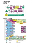
Page 56: ...LC 42SB45U 56 CHAPTER 6 BLOCK DIAGRAM WIRING DIAGRAM 1 MT5382 POWER MAGAGEMENT BLOCK DIAGRAM ...
Page 57: ...2008 03 14 LC 42SB45U 57 2 MAIN BOARD BLOCK DIAGRAM ...
Page 58: ...LC 42SB45U 58 3 WIRING DIAGRAM ...
Page 60: ...60 LC 42SB45U MAIN Unit Side B ...
Page 61: ...LC 42SB45U 1 POWER UNIT PRINTED WIRING BOARD POWER Unit Side A 61 ...
Page 62: ...LC 42SB45U POWER Unit Side B 62 ...
Page 64: ...64 LC 42SB45U IR Unit Side A 3 IR UNIT PRINTED WIRING BOARD IR Unit Side A Cn001 A2 ...

