


AL-1661CS UNPACKING AND INSTALLATION 5 - 10
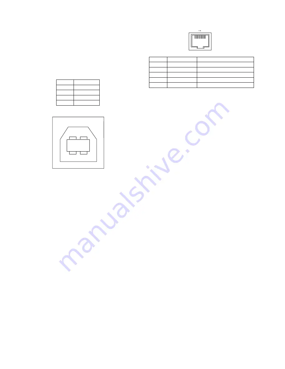
10. Interface
A. USB
Connector
4-pin ACON UBR23-4K2200
Type-B connector
Cable
Shielded twisted pair cable
(2 m (6 feet) Max.: high-speed transmission equivalent)
Pin configuration
The pin numbers and signal names are listed in the following table.
11. Moving
Moving instructions
When moving the unit, follow the procedure below.
Note: When moving this unit, be sure to remove the TD cartridge in
advance.
1) Turn the power switch off and remove the power cord from the out-
let.
2) Open the side cover and front cover, in that order. Remove the TD
cartridge and close the front cover and side cover, in that order.
To open and close the side cover and front cover, and to remove
the TD cartridge.
3) Raise the handle of the paper tray and pull the paper tray out until it
stops.
4) Push the center of the pressure plate down until it locks in place
and lock the plate using the pressure plate lock which has been
stored in the front of the paper tray.
5) Push the paper tray back into the unit.
6) Lock the scan head locking switch.
Note: When shipping the unit, the scan head locking switch must be
locked to prevent shipping damage.
7) Close the multi-bypass tray and the paper output tray extension,
and attach the packing materials and tape which were removed
during installation of the unit.
8) Pack the unit into the carton.
B. RJ45
RJ-45 connector pin arrangement
Pin No.
Signal name
1
+5V
2
-DATA
3
+DATA
4
GND
1
2
3
4
Pin No.
Signal name
LAN adapter RJ-45 connector
1
TD +
Send
2
TD –
Send output -
3
RD +
Receive input +
6
RD –
Receive input -
4, 5, 7, 8
Not used.
Not used.
1
8
Summary of Contents for AL-1661CS
Page 201: ...AL 1661CS CIRCUIT DIAGRAM 13 40 6 7 8 9 10 11 12 6 7 8 9 10 11 12 A B C D E F G H 1 1 ...
Page 212: ...Memo ...
Page 213: ...Memo ...