23
AH-S22AW2
AH-S25AW2
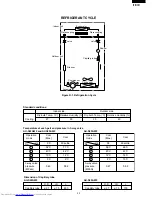
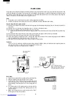
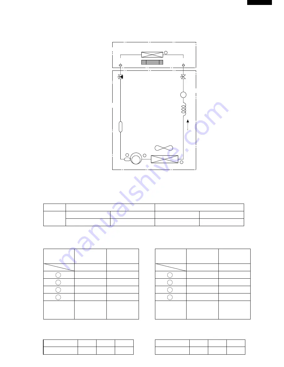
Figure R-1. Refrigeration Cycle
REFRIGERANT CYCLE
s
1
2
Capillary tube
3
Strainer
Outdoor unit
Condenser
Evaporator
Indoor unit
Compressor
Flare coupling
Flare coupling
Silencer
4
valve
valve
Accumulator
Indoor side
Standard conditions:
Dry-bulb Temp. (˚C)
Relative Humidity (%)
27
Cooling
50
Outdoor side
Dry-bulb Temp. (˚C)
Relative Humidity (%)
35
40
Temperature at each part and pressure in 3-way valve
AU-S22AW2 and AUS25AW2
Operation
mode
Cool
(Max.)
Cool
1
2
3
4
3-way valve
pressure
(MPaG)
92˚C
40˚C
10˚C
5˚C
0.46
71˚C
42˚C
12˚C
9˚C
0.56
90
60 settle
No.
Hz
Operation
mode
Cool
(Max.)
Cool
1
2
3
4
3-way valve
pressure
(MPaG)
96˚C
40˚C
12˚C
4˚C
0.47
66˚C
42˚C
14˚C
10˚C
0.58
94
60 settle
No.
Hz
Capillary tube
O.D
I.D.
L
ø 2.7
ø 1.5
800
Dimension of Capillary tube
AU-S22AW2
Capillary tube
O.D
I.D.
L
ø 2.7
ø 1.5
700
AU-S25AW2
AU-S25AW2

