background image

-12

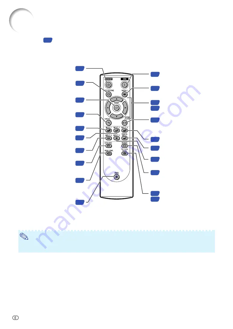
Remote Control

Adjustment buttons
(

'

/

"

/

\

/

|

)

38

30

MENU button

Display adjustment and setting 
screens.

38

ON button

Turn the power on.

28

30

ZOOM/FOCUS button

Adjust the projected image 
size or adjusting the focus.

29

INPUT 3 button

29

INPUT 5 button

34

34
44

RESIZE button

Switch the picture display
(STRETCH, SIDE BAR, etc.).

29

DIGITAL INPUT button

PICTURE MODE button

Select the picture setting (Memory) 
stored in “Picture Mode” on the 
“Picture” menu.

28

STANDBY button

Put the projector into standby 

mode.

32

KEYSTONE button

Enter the Keystone 

Correction mode.

39

ENTER button

Set items selected or 

adjusted on the menu.

34

UNDO button

Undo an operation or returning to 

the previous display.

29

INPUT 1 button

29

INPUT 2 button

29

INPUT 4 button

46

AUTO SYNC button

Automatically adjust images when 

connected to a computer.

48

RGB/COMP. button

Switch the signal type

(RGB or Component).

34

IRIS button

Switch “HIGH BRIGHTNESS 

MODE” or “HIGH CONTRAST 

MODE”.

Numbers in 

 refer to the main pages in this operation manual where the topic is explained.

Note

All the buttons on the remote control are made of luminous material that is visible in the dark. Visibility will
diminish over time. Exposure to light will recharge the luminous buttons.

Part Names and Functions

XV-Z2000U_E_P06_15.p65

04.10.13, 0:13 PM

12

Summary of Contents for AH-57201

Page 1: ...XV Z2000 ENGLISH FRANÇAIS ESPAÑOL PORTUGUÊS OPERATION MANUAL MODE D EMPLOI MANUAL DE OPERACION MANUAL DE OPERAÇÃO PROJECTOR PROJECTEUR PROYECTOR PROJETOR ...

Page 2: ...he REGISTRATION CARD packed with the projector 1 WARRANTY This is to assure that you immediately receive the full benefit of the parts service and labor warranty applicable to your purchase 2 CONSUMER PRODUCT SAFETY ACT To ensure that you will promptly receive any safety notification of inspection modification or recall that SHARP may be required to give under the 1972 Consumer Product Safety Act ...

Page 3: ...rojector utilises tin lead solder and a pressurised lamp containing a small amount of mercury Disposal of these materials may be regulated due to environmental considerations For disposal or recycling information please contact your local authorities or if you are located in the United States of America the Electronic Industries Alliance www eiae org Declaration of Conformity SHARP PROJECTOR MODEL...

Page 4: ... conform to This unit has some inactive pixels within acceptable tolerances which may result in inactive dots on the picture screen This will not affect the picture quality or the life expectancy of the unit DLPTM Digital Light Processing and DMDTM Digital Micromirror Device are trademarks of Texas Instru ments Inc Microsoft and Windows are registered trademarks of Microsoft Corporation in the Uni...

Page 5: ...2 Adjusting the Color Temperature 42 Gamma Correction Function 43 Emphasising the Contrast 43 Picture Mode Function 44 Switching the High Brightness High Contrast Mode 44 Computer Image Adjustment Fine Sync menu 45 Adjusting the Computer Image 45 Special Modes Setting 45 Auto Sync Adjustment 46 Checking the Input Signal 46 Using the Options Menu 47 Checking the Lamp Life Status 47 Setting On scree...

Page 6: ...ck with your nearest Authorized SharpVision Service Center or Dealer Lens cap attached PCAPHA021WJSA Supplied accessories Optional accessories Operation manual TINS B529WJZZ Marks Used in This Operation Manual Info Indicates safeguards when using the projector Note Indicates additional information for setting up and operating the projector In this operation manual the illustration and the screen d...

Page 7: ... paying particular attention to cords at plugs convenience receptacles and the point where they exit from the product 14 Lightning For added protection for this product during a lightning storm or when it is left unattended and unused for long periods of time unplug it from the wall outlet and disconnect the cable system This will prevent damage to the product due to lightning and power line surge...

Page 8: ...aximum angle of 12 degrees Placement should be within 12 degrees of horizontal Warning about placing the projector in a high position When placing the projector in a high posi tion ensure to secure it carefully to avoid personal injury caused by the projector fall ing down Do not subject the projector to hard im pact and or vibration Take care with the lens so as not to hit or damage the surface o...

Page 9: ...or instructions on how to make the connections Using the projector in other countries The power supply voltage and the shape of the plug may vary depending on the region or country you are using the projector in When using the projector overseas ensure to use an appropriate power cord for the coun try you are in Temperature monitor function If the projector starts to overheat due to setup problems...

Page 10: ...ton Display adjustment and setting screens 39 ENTER button Set items selected or adjusted on the menu 34 UNDO button Undo an operation or returning to the previous display 28 STANDBY button Put the projector into standby mode 34 RESIZE button Switch the picture display STRETCH SIDE BAR etc 28 ON button Turn the power on Projector Part Names and Functions Attaching the lens cap Push the lens cap on...

Page 11: ...wer on Temperature warning indicator Off Normal Red on The internal temperature is abnormally high See page 54 Lamp indicator Green on Normal Green blinks The lamp is warming up or shutting down Red on The lamp has been shut down abnormally or needs to be changed See page 54 Part Names and Functions ...

Page 12: ... Security Standard connector 31 53 7 Rear adjustment feet Intake vent Exhaust vent The speed and pitch of the cooling fan may change during operation in response to internal temperature changes This is normal operation and does not indicate a malfunction 53 7 21 INPUT 2 terminal Component signals Digital input type switch 22 INPUT 5 DIGITAL terminal 21 22 23 23 25 26 25 26 INPUT 1 terminal Compone...

Page 13: ...he Keystone Correction mode 39 ENTER button Set items selected or adjusted on the menu 34 UNDO button Undo an operation or returning to the previous display 29 INPUT 1 button 29 INPUT 2 button 29 INPUT 4 button 46 AUTO SYNC button Automatically adjust images when connected to a computer 48 RGB COMP button Switch the signal type RGB or Component 34 IRIS button Switch HIGH BRIGHTNESS MODE or HIGH CO...

Page 14: ...emote control once they have run out as leaving them in can cause them to leak Battery fluid from leaked batteries is harmful to skin therefore ensure to first wipe them and then remove them using a cloth The batteries included with this projector may run down in a short period depending on how they are kept Ensure to replace them as soon as possible with new batteries Usable Range The remote cont...

Page 15: ...control On the projector This section shows the basic operation For details see the page described below for each step Setup and Projection Connection of the projector and the video equipment with an S video terminal is explained as an example below 2 Connect the projector to the video equipment and plug the power cord into the AC socket of the projector 3 Remove the lens cap and turn the projecto...

Page 16: ...s On the remote control On the projector 1 Press 2 Adjust the focus by pressing or 2 Adjust the projected image size by adjusting zoom On the remote control On the projector 1 Press 2 Adjust the zoom by pressing or 1 Press 2 Adjust the zoom by pressing or 1 Press 2 Adjust the focus by pressing or 8 Turn the Power off Press the STANDBY button then press that button again while the confirmation mess...

Page 17: ...aking viewing difficult Close the curtains and dim the lights when setting up the projector in a sunny or bright room Standard Setup Front Projection Place the projector at the required distance from the screen according to the desired picture size See page 17 Setting Up the Projector Indication of the Projection Image Size and Projection Distance See Screen Size and Projection Distance on page 17...

Page 18: ...ues χ Picture size diag inches L Projection distance ft m L1 Minimum projection distance ft m L2 Maximum projection distance ft m H Distance from the bottom of the image to the lens center in cm Distance from the bottom of the image to the lens center H When using a wide screen 16 9 In case of displaying the 16 9 picture on the whole of the 16 9 screen When using a normal screen 4 3 In case of set...

Page 19: ... page 52 Info When using a mirror ensure to carefully position both the projector and the mirror so the light does not shine into the eyes of the audience Ceiling mount Setup It is recommended that you use the optional Sharp ceiling mount bracket for this installation Before mounting the projector contact your nearest Authorized SharpVision Service Center or Dealer to obtain the recommended ceilin...

Page 20: ... See pages 25 26 INPUT 3 terminal Connecting video equipment with S video output terminal VCR DVD player etc See page 24 INPUT 1 2 terminal Connecting video equipment with component output terminal DVD player DTV decoder DVD recorder with hard disc etc See page 21 INPUT 4 terminal Connecting video equipment without S video output terminal See page 24 RS 232C terminal Connecting the computer to con...

Page 21: ...ble RS 232C terminal Cable Component cable commercially available Dedicated cable attached to the connected equipment DVI cable sold separately AN C3DV Video cable commercially available Dedicated cable attached to the connected equipment S video cable commercially available Dedicated cable attached to the connected equipment RS 232C cable commercially available Samples of Cables for Connection Fo...

Page 22: ...l connections turn on the projector and then the other devices Ensure to read the operation manuals of the devices to be connected before making connections When connecting the component video equipment to the component input terminal on the projector INPUT 1 or INPUT 2 Component cable commercially available INPUT 1 or INPUT 2 terminal Analog component output terminal DVD Player etc 1 2 ...

Page 23: ...elect RGB for Signal Type on the OSD menu or press on the remote control See page 48 When connecting the component video equipment to the DVI input terminal on the projector INPUT 5 Before connecting the cable switch the digital input type switch to VIDEO Note For this connection select Component for Signal Type on the OSD menu or press on the remote control See page 48 INPUT 5 terminal DVI to 15 ...

Page 24: ...witch to VIDEO DVD Player etc 2 3 1 Note Select DIGITAL mode when connecting to video equipment with the digital output terminal See page 29 When connecting the video equipment with DVI output terminal DIGITAL INPUT Before connecting the cable switch the digital input type switch to VIDEO ...

Page 25: ...ting video equipment with video output terminal INPUT 4 S video cable commercially available S video output terminal INPUT 3 terminal DVD Player etc 2 1 INPUT 4 terminal Video output terminal Composite video cable commercially available DVD Player etc 1 2 Connecting to Video Equipment ...

Page 26: ...some of the functions not to work When connecting the projector to a computer in this way select RGB for Signal Type on the OSD menu or press on the remote control See page 48 A Macintosh adaptor may be required for use with some Macintosh computers Contact your nearest Authorized SharpVision Service Center or Dealer Depending on the computer you are using an image may not be projected unless the ...

Page 27: ...mputer to be connected After making all connections turn on the projector and then the computer Plug and Play function This projector is compatible with VESA standard DDC 1 DDC 2B The projector and a VESA DDC com patible computer will communicate their setting requirements allowing for quick and easy setup Before using the Plug and Play function ensure to turn on the projector first and the connec...

Page 28: ... terminal is not correctly set up Refer to the operation manual of the computer for details See RS 232C Specifications and Command Settings on page 60 for details Info Do not connect the RS 232C cable to a port other than the RS 232C terminal on the computer This may damage your computer or projector Do not connect or disconnect an RS 232C serial control cable to or from the computer while it is o...

Page 29: ... projector or on the remote control The power indicator illuminates green After the lamp indicator illuminates the projec tor is ready to start operation Note The lamp indicator illuminates or blinks in dicating the status of the lamp Green The lamp is ready Blinking green The lamp is warming up or shutting down Red The lamp is shut down abnormally or the lamp should be replaced When switching on ...

Page 30: ... projecting images from equipment connected to INPUT 1 terminals Used for projecting images from equipment connected to INPUT 2 terminal Used for projecting images from equipment connected to INPUT 3 terminal Used for projecting images from equipment connected to INPUT 4 terminal Used for projecting images from equipment connected to INPUT 5 terminal Used for projecting images from equipment with ...

Page 31: ... the remote control 2 Press or on the remote con trol to adjust the focus Note You can also adjust the focus by using and or on the projector Adjusting the Projected Image Size 1 Press on the remote control 2 Press or on the remote con trol to adjust the zoom Note You can also adjust the zoom by using and or on the projector ...

Page 32: ...urface is diffi cult to slide In this case pull the pro jector back slightly and adjust its height 2 Remove your hands from the HEIGHT ADJUST button of the projector after its height has been finely adjusted 3 Finely adjust the height and in clination by turning the rear ad justment feet Note When adjusting the projected image position trapezoidal distortion occurs In this case see Keystone Correc...

Page 33: ... distortion is called Keystone Correction 1 Press on the remote control to enter the Keystone Correction mode 2 Press toselect HKeystone or V Keystone 3 Press to move the mark on the selected adjustment item to the desired setting Note Straight lines and the edges of the dis played image may appear jagged when adjusting the Keystone setting When adjusting H Keystone and V Keystone at the same time...

Page 34: ... Keystone correction function onto the screen Adjust the focus until the image on the screen comes into focus See page 30 ZOOM FOCUS END ZOOM FOCUS 2 Change the projection angle moving the projector or using the adjuster to properly project images onto the screen See page 31 3 Align the edge of the screen closest to the projector with the test pattern by adjusting the zoom and the adjsuter See pag...

Page 35: ...ressed while the display is on the mode is switched between HIGH BRIGHTNESS MODE and HIGH CONTRAST MODE Note This function can also be accessed from the OSD menu see page 44 Adjusting the Picture Aspect Ratio This function allows you to modify or customize the picture display mode to enhance the input image Depending on the input signal you can choose STRETCH SIDE BAR SMART STRETCH or CINEMA ZOOM ...

Page 36: ... 9 aspect ratio 4 3 aspect ratio Note SMART STRETCH cannot be selected while the Keystone correction page 32 is being adjusted Keystone correction page 32 is disabled while the picture mode is set to SMART STRETCH 580I 580P is displayed on the screen when signal 576I 576P is input STRETCH is fixed when 540P 720P or 1080I signal is entered SMART STRETCH cannot be selected while input signal from a ...

Page 37: ...ntrast 5500K 6500K 7500K 8500K 9300K 10500K Main Menu Sub Menu CLR Temp Page 42 Page 42 Page 42 Page 43 Page 43 Page 44 Page 44 1 1 1 1 Items when selecting INPUT 1 2 3 4 or when inputting component signal through INPUT 5 Standard Cinema 1 Cinema 2 Cinema 3 Gamma Adj Bright Boost ON OFF Picture Mode Memory 1 Memory 2 Memory 3 Memory 4 Memory 5 Memory OFF 10 0 3 3 3 3 3 3 3 3 10 0 10 0 10 0 10 0 10...

Page 38: ...ft Lower Left Menu Position Page 47 Page 47 Page 47 Page 48 Page 49 Page 49 Page 50 Page 50 Page 51 1 2 1 Item when selecting INPUT 3 or INPUT 4 2 Item when selecting INPUT 5 RGB Component Signal Type Menu Color Opaque Translucent Page 48 Main Menu English Deutsch Español Nederlands Français Italiano Svenska Português Language Page 52 PRJ Mode menu PRJ Mode Front Ceiling Front Rear Ceiling Rear Pa...

Page 39: ...tings For setting the menu items see pages 40 and 41 Menu Selections Adjustments This operation can also be performed by using the buttons on the projector 1 Press The Picture menu screen for the selected input mode is displayed 2 Press or to display the other menu screens The menu icon for the selected menu screen is highlighted Note The Fine Sync menu is not available for selecting INPUT 3 or 4 ...

Page 40: ...wing it Press The selected single adjustment item e g Bright appears on the lower part of the screen When pressing or the next item will be displayed e g Bright is replaced with Color by pressing Note Press to return to the previous screen 4 Press or to adjust the item se lected The adjustment is stored 5 Press The menu screen will disappear Single adjustment items ...

Page 41: ...le Picture menu screen for INPUT 1 mode Menu Selections Settings This operation can also be performed by using the buttons on the projector 1 Press The Picture menu screen for the selected input mode is displayed 2 Press or to display the other menu screens The menu icon for the selected menu screen is highlighted Note The Fine Sync menu is not available for selecting INPUT 3 or 4 Menu icon Menu s...

Page 42: ...u The selected item is highlighted Example Selecting Menu Position Note Press or to return to the previous screen For some items press or to select the icon using 4 Press or to select the setting of the item displayed in the sub menu 5 Press The selected item is set 6 Press The menu screen will disappear ...

Page 43: ...harpness For stronger red For stronger blue Adjusting the Color Temperature This function allows for selecting the desired color temperature With the lower value selected the projected image becomes warmer reddish and incandescent like while with the higher value the image becomes cooler bluish and fluo rescent like Menu operation Page 40 Example Picture menu screen for INPUT 1 mode Description of...

Page 44: ...er With the higher value selected the projected image becomes brighter Pressing or changes the value of the Gamma in the sub menu Selectable Items Standard Cinema 1 Cinema 2 Cinema 3 Description Standard picture without gamma correction Gives greater depth to darker portions of images Brightness is toned down and the image becomes more balanced Brighten the darker portions of images for easier vie...

Page 45: ...mory location for those settings and make settings on the Picture menu Picture Mode Memory 1 5 Memory OFF Description Settings of all items in Picture can be stored for the respective input modes The stored settings Memory 1 to 5 can be selected in any input modes Besides Memory 1 to Memory 5 other settings on the Picture menu can be stored for each input mode The settings stored in Memory OFF can...

Page 46: ...al To reset all adjustment items select Reset and press Selectable items Clock Phase H Pos V Pos Description Adjusts vertical noise Adjusts horizontal noise similar to tracking on your VCR Centers the on screen image by moving it to the left or right Centers the on screen image by moving it up or down Special Modes Setting Ordinarily the type of input signal is detected and the correct resolution ...

Page 47: ... image cannot be achieved with Auto Sync adjustment use manual adjust ments See page 45 Auto Sync cannot be used in the DIGITAL mode Checking the Input Signal This function allows you to check the current in put signal information Menu operation Page 40 Example Fine Sync menu screen for INPUT 5 RGB mode Note 540P is displayed on the screen when signal 1080I is inputted during DVI connection Select...

Page 48: ... shown depending on the frequency at which Eco Mode is switched to Eco mode and Standard mode See page 49 The lamp life may vary depending on the usage condition Using the Options Menu Lamp usage condition Life Operated exclusively in Eco mode Operated exclusively in Standard mode Remaining lamp life 100 5 Approx Approx 3 000 hours 150 hours Approx Approx 2 000 hours 100 hours Setting On screen Di...

Page 49: ... menu for PAL M and PAL N input sig nals Description When connected to PAL video equip ment When connected to NTSC video equipment When connected to SECAM video equipment When reproducing NTSC signals in PAL video equipment Selectable items PAL NTSC3 58 SECAM NTSC4 43 Signal Type Setting This function allows you to select the input sig nal type RGB or Component for INPUT 5 Menu operation Page 40 E...

Page 50: ...s 15 Brightness 85 100 Selectable items Eco mode Standard mode Power consumption When using AC 100V 315 W 360 W Lamp life Approx 3 000 hours Approx 2 000 hours Selecting a Background Image This function allows you to select the image dis played when no signal is being sent to the pro jector Menu operation Page 40 Example Options menu screen for INPUT 1 mode Description of Background Images Selecta...

Page 51: ...l be disabled Selectable items ON OFF Selecting the Menu Screen Position This function allows you to select the desired position of the menu screen Menu operation Page 40 Example Options menu screen for INPUT 1 mode Description of Menu Positions Description Displayed on the center of the image Displayed on the upper right of the image Displayed on the lower right of the image Displayed on the uppe...

Page 52: ...olor of the menu screen Menu operation Page 40 Example Options menu screen for INPUT 1 mode Description of Menu Colors The menu is displayed opaquely The menu is displayed translucently The part of the menu on the image becomes transparent Opaque Translucent Selectable Items Description ...

Page 53: ...een display 4 Press The Language menu will disappear Note This procedure can also be performed by using the buttons on the projector Selecting the On screen Display Language and the Projection Mode Setting the Projection Mode This projector is equipped with a reverse invert image function that allows you to reverse or in vert the projected image for various applications Menu operation Page 40 Exam...

Page 54: ...aning the projector Ensure to unplug the power cord before cleaning the projector The cabinet as well as the operation panel is made of plastic Avoid using benzene or thinner as these can damage the finish on the cabinet Do not use volatile agents such as insecticides on the projector Do not attach rubber or plastic items to the projec tor for long periods The effects of some of the agents in the ...

Page 55: ...minate in the lower left corner of the picture If the temperature keeps on rising the lamp will turn off and the temperature warning indicator will blink the cooling fan will run for a further 90 seconds and then the projector will enter the standby mode After appears ensure to perform the measures described on page 55 About the lamp indicator When the remaining lamp life becomes 5 or less yellow ...

Page 56: ...ss Green on Green blinks when the lamp is warming up or shutting down Info If the temperature warning indicator illuminates and the projector enters the standby mode check whether any of the ventilation holes are blocked page 7 and then try turning the power back on Wait until the projector has cooled down completely before plugging in the power cord and turning the power back on At least 10 minut...

Page 57: ...se It is important to note that failure can often result in the bulb cracking When the lamp replacement indicator and on screen display icon are illuminated it is recommended that the lamp be replaced with a new one immediately even if the lamp appears to be operating normally Should the lamp break the glass particles may spread inside the lamp cage or gas contained in the lamp may be vented into ...

Page 58: ...d Unplug the power cord from the AC socket Leave the lamp until it has fully cooled down about 1 hour 3 Remove the lamp unit cover Turn the projector over Loosen the user service screw 1 that secures the lamp unit cover Hold the tab and slide to wards the direction of the arrow to re move the lamp unit cover 2 AC socket STANDBY button 1 2 User service screw for lamp unit cover Tab Tab Removing and...

Page 59: ... power will not turn on even if the power cord is connected to the projector Resetting the Lamp Timer Reset the lamp timer after replacing the lamp Info Make sure to reset the lamp timer only when replacing the lamp If you reset the lamp timer and continue to use the same lamp this may cause the lamp to become damaged or explode 1 Connect the power cord Plug the power cord into the AC socket of th...

Page 60: ... Not connected C4 Not connected 14 5V power C5 Ground 15 Ground DVI Analog RGB Input Pin No Signal Pin No Signal 1 Not connected 16 Hot plug detection 2 Not connected 17 Not connected 3 Not connected 18 Not connected 4 Not connected 19 Not connected 5 Not connected 20 Not connected 6 DDC clock 21 Not connected 7 DDC data 22 Not connected 8 Vertical sync 23 Not connected 9 Not connected 24 Not conn...

Page 61: ...ector is verified When using the computer control function of the projector the projector s operating status cannot be read by the computer Commands Example When power on Response code format Normal response Problem response communication error or incorrect command Command format RS 232C Specifications and Command Settings Return code 0DH C1 C2 C3 C4 P1 P2 P3 P4 Command 4 digit Parameter 4 digit O...

Page 62: ... be projected adjust the output signal of your computer and so forth while referring to the table below 15 7 31 5 33 8 15 6 31 3 45 0 28 1 33 8 28 1 33 8 480I 480P 540P 576I 576P 720P 1035I 1035I 1080I 1080I 60 60 60 50 50 60 50 60 50 60 Signal Vertical Frequency Hz Horizontal Frequency kHz PC MAC WS Horizontal Frequency kHz Vertical Frequency Hz VGA PC SVGA XGA VESA Standard DVI Support Resolutio...

Page 63: ... runs faster The lamp will eventually need to be changed The lamp has reached the end of its life Replace the lamp Change the input signal type Problem On screen display does not appear An unusual sound is occasionally heard from the cabinet Maintenance indicator illuminates or blinks in red The cooling fan becomes noisy The lamp takes a long time to turn on Picture is dark Image is green on INPUT...

Page 64: ...B 0 7 Vp p 75 Ω terminated PR CR 0 7 Vp p 75 Ω terminated 29 pin DVI I terminal Digital Input impedance 50 Ω Input level 250 1000 mV Analog Input impedance 75 Ω Input level 0 7 Vp p Y 1 0 Vp p sync negative 75 Ω terminated PB CB 0 7 Vp p 75 Ω terminated PR CR 0 7 Vp p 75 Ω terminated Synchronization signal Separate sync Composite sync Input level TTL level Input impedance 1 KΩ Green on sync Input ...

Page 65: ...nt View Bottom View M4 M4 M4 M4 9 64 3 25 11 7 64 282 1 16 1 5 2 11 64 55 05 12 7 32 310 1 59 64 48 5 3 33 64 89 13 64 5 2 3 16 55 5 3 15 16 99 95 5 7 64 129 5 5 7 64 129 5 5 8 15 5 9 16 14 4 3 16 106 3 8 9 32 210 3 8 7 8 225 3 1 7 32 30 9 1 5 32 29 1 1 7 32 30 9 1 3 4 44 1 ...

Page 66: ...ty resizing of lower and higher resolu tion images to fit the projector s native resolution Keystone Correction Function to digitally correct a distorted image when the projector is set up at an angle smoothes out jaggies on keystone images and compresses the image not only horizontally but vertically keeping the 16 9 aspect ratio Phase Phase shift is a timing shift between isomorphic signals with...

Page 67: ... Lock 11 KEYSTONE button 32 Keystone Correction 32 L Lamp 56 Lamp indicator 54 Lamp Timer Life 47 Language 52 Lens cap 9 M MENU button 38 Menu Color 51 Menu Position 50 O ON button 28 On screen display language 52 OSD Display 47 P Phase 45 Picture 42 Picture Mode 44 PICTURE MODE button 34 Power cord 28 Power indicator 10 PRJ mode 52 R Rear 52 Rear adjustment feet 31 Red 42 Remote control 12 Remote...

Page 68: ...gence strict liability or otherwise In no event shall Sharp be liable or in any way responsible for any damages or defects in the Product which were caused by repairs or attempted repairs performed by anyone other than an authorized servicer Nor shall Sharp be liable or in any way responsible for any incidental or consequential economic or property damage Some states do not allow the exclusion of ...

Page 69: ...out appropriate model serial number and CSA cUL markings h Any products used for rental or commercial purposes i Any installation setup and or programming charges Should this Sharp product fail to operate during the warranty period warranty service may be obtained upon delivery of the Sharp product together with proof of purchase and a copy of this LIMITED WARRANTY statement to an Authorized Sharp...

Page 70: ...Printed in China Imprimé en Chine Impreso en China Impresso na China TINS B529WJZZ 04P11 CNM SHARP CORPORATION ...

Reviews: