GB-2
ENGLISH
A
B
B
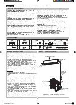
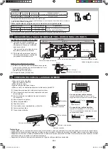
PIPING
Max. piping
length:A
Max. height
difference:B
Min. piping
length
Additional refrigerant
Piping length exceeds 24.6 ft (7.5 m)
98.4 ft (30 m) 32.8 ft (10 m)
9.8 ft (3 m)
0.5 oz/ft (50 g/m)
• Standard piping length is 24.6 ft (7.5 m).
• When the outdoor unit is placed at a higher level than the indoor unit, provide a trap near the hose’s lead-in port.
Use the refrigerant pipes shown in the table below.
Pipe size
Pipe thickness
Thermal insulation
Liquid side
1/4" (ø 6.35 mm)
0.03 inch(0.8 mm)
Thickness: 0.24inch (6 mm) or thicker
Material: Polyethylene foam
Gas side
5/8" (ø 15.88 mm)
0.04 inch (1.0 mm)
• The thermal insulation should cover both the gas and liquid pipes.
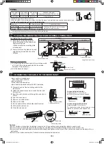
Trap
Center of wall hole
Length unit: inch (mm)
Center of wall hole
Outline of indoor unit
Wall
Making a piping hole
(1) Drill a piping hole with concrete drill or a hole saw with
a 0.2 inch (5 mm) down ward slant to the outside.
Diameter: 2.6inch (65mm)
(2) Set the sleeve and caps.
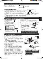
1 PLACING THE MOUNTING PLATE AND MAKING A PIPING HOLE
Installing the mounting plate
(1) Referring to the the figure below,
mark the location for the fixing holes
and the piping hole.
• Make sure that the mounting plate
is horizontally.
(2) Secure the mounting plate to the wall
with the long screws and check the
stiffness.
Indoor
Outdoor
Cut with a saw.
Cap
0.2 inch (5 mm)
Sleeve (Downward to outdoor)
L1’ S
G
L2’
• Use a solid or stranded wire.
Connecting cable: AWG14
• Use copper wire.
• Follow local electrical codes.
• Use a double insulated cable with 600 V insulation.
Cable cover
Connecting cable
Earth wire
Terminal board
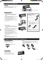
2 CONNECTING THE CABLE TO THE INDOOR UNIT
Conduit holder
Conduit connector
Lock nut
In case using solid wires
Stripping length: 0.7 inch (18 mm)
Be sure to make the wire hook-shaped.
In case using stranded wires
Stripping length: 0.3 inch (8 mm)
For power supply cable, securely clamp a round
terminal to each end of the stripped wire.
Cautions:
• Be very careful not to confuse the terminal connections. Wrong cabling may damage the internal control circuit.
• Be sure to connect the cable to match the markings on the indoor unit’s terminal board and those of the outdoor unit.
• Be sure to put the cable leads deep into the terminal board and tighten up the screws. Poor contact can cause overheating or fire, or
malfunction.
• Be sure to use a disconnect switch. Follow the local and state electrical codes.
(1) Process the end of the connecting cable for the
indoor side.
(2) Attach the conduit connector to conduit holder with
the lock nut.
(3) Insert the cable into the unit through the conduit con-
nector.
(4) Open the open panel.
(5) Remove the cable holder.
(6) Connect the cable.
(7) Fix the cable with the cable holder and the screw.
(8) Put back the cable cover.
(9) Close the open panel.
Earth wire
2.0 inch (50 mm)
2.4 inch (60 mm)
Copper wire
0.7 inch (18 mm)
Round terminal
Copper wire
0.3 inch (8 mm)
Screw
29.4 (746)
13.1 (333)
9.8 (248)
11.3 (286)
2 (51)
4 (102)
12.3 (313)
ø2.6(65)
1.6 (41)
ø2.6(65)
52.2 (1327)
AYX36RU_IM_3_lang.indb 2
2014-09-12 07:59:33


