17
17-1
17-2
25WF30
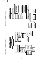
TROUBLE SHOOTING T
ABLE
(Continued)
SET
Sub-
colour
.
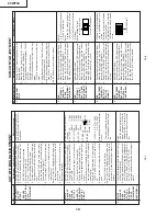
Check IC800
and its
peripherals.
C
COLOUR PR
ODUCED
Colour in B/W mode.
Colour control circuit detective.
Colour saturation control does not
work.
Fix control to coloured system.
T
urn colour control to minimum.
Does colour disappear?
T
urn up and down colour control.
Does colour gain go up and
down?
Can the sub-colour be readjusted
in service mode?
T
urn on colour system forced
switch. Does colour appear?
APG circuit:
Check IC800
and its
peripherals.
Ye
s
Y
e
s
White
balance:
Check RGB
output circuit
of IC800.
Check IC800.
No
Ye
s
N
o
Check D1664 and its
peripherals.
P
AL, SECAM, NTSC4.43:
Check X800, pin (12) of IC800 and
their peripherals.
No
No
Is chroma input level at pin (43) of
IC800 proper?
Ref. value: 100 ~ 500mVp-p.
Ye
s
Fix control to
coloured system.
No
Is SCP
signal waveform at pin
(30) of IC800 proper?
Are signal waveforms at
TP801 and
TP802
proper?
Ye
s
Ye
s
Check Q400 and its
peripherals.
No
No
Ye
s
Check IC800.
Summary of Contents for 25WF30
Page 18: ...6 5 4 3 2 1 A B C D E F G H 18 25WF30 CHASSIS LAYOUT ...
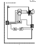
Page 19: ...6 5 4 3 2 1 A B C D E F G H 19 25WF30 BLOCK DIAGRAM 1 ...
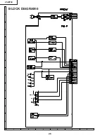
Page 23: ...6 5 4 3 2 1 A B C D E F G H 26 25WF30 BLOCK DIAGRAM 5 ...
Page 26: ...6 5 4 3 2 1 A B C D E F G H 29 25WF30 SCHEMATIC DIAGRAM CRT Unit ...
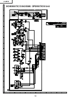
Page 30: ...6 5 4 3 2 1 A B C D E F G H 36 25WF30 SCHEMATIC DIAGRAM OPERATION Unit ...
Page 35: ...6 5 4 3 2 1 A B C D E F G H 44 25WF30 PWB D OPERATION Unit Wiring Side ...


