


13
13-1
13-2
25WF30
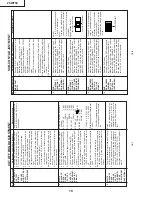
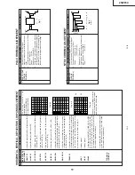
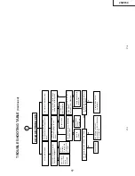
TROUBLE SHOOTING T
ABLE
Check the voltage at pin (6) of IC1501.
NO VER
TICAL
SCAN
Check IC1501 and
related circuits.
Normal
Abnormal
Normal
Check IC800 and its
peripheral parts.
Check vertical trigger pulse at pin (26) of IC800.
Check D1576 and R1576.
Abnormal
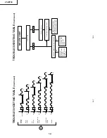
Does D1200 (Power LED) turn on?
D1200 (Power LED) turn on and of
f.
NO RASTER
Normal
Check CR
T
connector (KY), (H) bias.
Is pin (10) of IC700 in "L" level ?
Abnormal
Check IC850.
Check
protecter circuit
and its related
parts pin (2) of
IC1000 vertical
pulse.
Check the
power circuit
consisting of
IC700, Q700
IC750 and
IC602.
Ye
s
Y
es (RED)
Ye
s
(Bus error)
No
See many often
D1200 flashes
in red.
This indicates
which IC to
check up.
No
A
Does horizontal circuit
momentary oscillate?
Check R1651,
IC800 and their
peripheral parts.
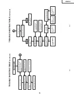
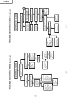
TROUBLE SHOOTING T
ABLE
(Continued)
Summary of Contents for 25WF30
Page 18: ...6 5 4 3 2 1 A B C D E F G H 18 25WF30 CHASSIS LAYOUT ...
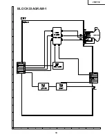
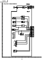
Page 19: ...6 5 4 3 2 1 A B C D E F G H 19 25WF30 BLOCK DIAGRAM 1 ...
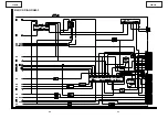
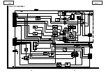
Page 23: ...6 5 4 3 2 1 A B C D E F G H 26 25WF30 BLOCK DIAGRAM 5 ...
Page 26: ...6 5 4 3 2 1 A B C D E F G H 29 25WF30 SCHEMATIC DIAGRAM CRT Unit ...
Page 30: ...6 5 4 3 2 1 A B C D E F G H 36 25WF30 SCHEMATIC DIAGRAM OPERATION Unit ...
Page 35: ...6 5 4 3 2 1 A B C D E F G H 44 25WF30 PWB D OPERATION Unit Wiring Side ...