12
12-1
12-2
25WF30
No.
Adjustment point
Adjustment Condition / Procedure
W
aveform or others
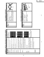
1
2
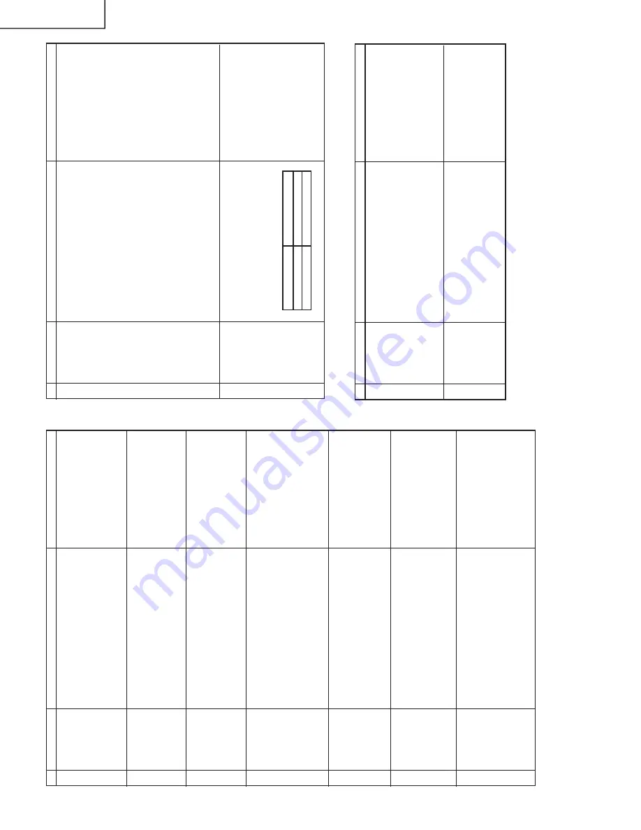
COLOUR Key
1.
Receive "Color Bar" signal.
2
.
Press to MENU mode, then Select Picture
Mode and set to select COLOUR.
3
.
Press V
olume Up/Down key to check whether
the COLOUR ef
fect is OK or not.
CONTRAST
Key
1.
Receive "Monoscope Pattern" signal.
2.
Press to MENU mode, then Select Picture
Mode and set to select CONTRAST
.
3
.
Press V
olume Up/Down key to check whether
the CONTRAST
ef
fect is OK or not.
FUNCTION OPERA
TION CHECKING (1) (VIDEO &
AUDIO)
3
BRIGHTNESS
1.
Receive "Monoscope Pattern" signal.
2
.
Press to MENU mode, then Select Picture
Mode and set to select BRIGHTNESS.
3
.
Press V
olume Up/Down key to check whether
the BRIGHTNESS ef
fect is OK or not.
4
TINT Key
1.
Receive the "NTSC Colour Bar" signal thru
A
V
in.
2
.
Press to MENU mode, then Select Picture
Mode and set to selectTINT
.
3.
Press V
olume Up/Down key to check
TINT
,
UP for GREEN direction and DOWN for RED
direction whether is OK or not.
5
SHARPNESS
Key
1.
Receive "Monoscope Pattern" signal.
2
.
Press to MENU mode, then Select Picture
Mode and set to select SHARPNESS.
3
.
Press V
olume Up/Down key to check whether
the SHARPNESS ef
fect is OK or not.
6
NORMAL Key
1.
Once in PICTURE Mode, and the NORMAL
key is pressed, all the settings will be present
to normal setting.
(Normal setting value for every mode, refer to
page 7-2.)
Notes:
If nothing is display mean contrast,
colour
, bright, tint, sharpness are
all in normal setting.
7
WHITE TEMP
1.
Receive the Monoscope Pattern signal.
2.
Set FUNCTION to select WHITE
TEMP
.
3.
Press V
olume Up/Down key to check WHITE
TEMP
Option, ST
ANDARD: NORMAL
S
E
T
-
TING, W
ARM for more REDDISH direction
changing, COOL for more BLUISH direction
changing.
No.
Adjustment point
Adjustment Condition / Procedure
W
aveform or others
FUNCTION OPERA
TION CHECKING (2) (VIDEO &
AUDIO)
9
HEADPHONE
OUTPUT
CHECKING
1.
Receive the P
A
L
Colour Bar signal with sound
400 Hz, 100% modulation (± 50 kHz Dev)
2.
Maximum volume, and check the headphone
output with 400 kHz sound and no sound out
from speaker
.
8
COLOUR
SYSTEM
1.
Receive the "P
AL
COLOUR BAR" signal thru
A
V
, press the COLOUR SYSTEM key to se-
lect modes except P
AL, check the COLOUR
is not working properly
.
Then, select the "P
AL"
mode. Check again its colour so that it is work-
ing properly
.
2.
Receive “NTSC 3.58” signal thru
A
V
, press
COLOUR SYSTEM key to select modes ex-
cept NTSC3.58, check the COLOUR is not
working properly
. Then, select the “NTSC 3.58”
mode. Check again its colour so that it is work-
ing properly
.
3.
Receive “NTSC 4.43 COLOUR BAR” signal
thru
A
V
, press COLOUR SYSTEM key to se-
lect modes except N4.43, check the COLOUR
is not working properly
. Then, select the “NTSC
4.43” mode. Check again its colour so that it
is working properly
.
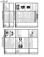
SUB-VOL
ADJ
H/P Output (Open)
63
1.0Vp-p
40
500mVp-p
No.
Adjustment point
Adjustment Condition / Procedure
W
aveform or others
PROTECT
OR OPERA
TION CHECKING
2
OTHER
PROTECT
OR
*
Correspondence for short circuit of smooth-
ing electrolysis of +B line and so on.
T
o
check the operation of the protector and
so on, take care for the breakage, deteriora-
tion and so on of each element.
1
H, V PROTEC-
TO
R
1.
Receive E-5CH "Monoscope Pattern" signal.
2
.Connect the Bias Box to D1621 cathode
(R1620 side).
3.
Set voltage of Bias Box to 15V and make sure
the protector is not work.
4.
Set voltage of Bias Box to 24V
, and make sure
the protector is work.
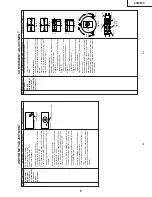
Reference
Approx. 17.7V as
ordinary
.
Summary of Contents for 25WF30
Page 18: ...6 5 4 3 2 1 A B C D E F G H 18 25WF30 CHASSIS LAYOUT ...
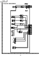
Page 19: ...6 5 4 3 2 1 A B C D E F G H 19 25WF30 BLOCK DIAGRAM 1 ...
Page 23: ...6 5 4 3 2 1 A B C D E F G H 26 25WF30 BLOCK DIAGRAM 5 ...
Page 26: ...6 5 4 3 2 1 A B C D E F G H 29 25WF30 SCHEMATIC DIAGRAM CRT Unit ...
Page 30: ...6 5 4 3 2 1 A B C D E F G H 36 25WF30 SCHEMATIC DIAGRAM OPERATION Unit ...
Page 35: ...6 5 4 3 2 1 A B C D E F G H 44 25WF30 PWB D OPERATION Unit Wiring Side ...


