


11
11-1
11-2
25WF30
No.
Adjustment point
Adjustment Condition / Procedure
W
aveform or others
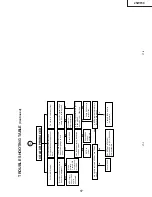
1
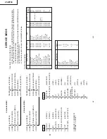
HORIZONT
AL, VERTICAL, DEFLECTION LOOP
AND
ADJUSTMENT
No.
Adjustment point
Adjustment Condition / Procedure
W
aveform or others
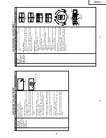
1
SUB COLOUR
(I
2
C BUS
CONTROL)
1.
Receive the P
A
L
Colour Bar signal.
2.
Make the image normal with the remote con-
troller
.
3.
Connect the oscilloscope to pin (4) of
TP802
(ky). (Use Probe10:1)
Range
: 2V/Div
Sweep
time
: 20µ sec/Div
4.
Set the sub colour adjustment mode with the
remote controlller
, and vary the sub colour data
to make 75% W of the colour bar and RED at
the same level for adjustment shown in
Fig. 7
.
P
A
L
CHROMA
ADJUSTMENT
No.
Adjustment point
Adjustment Condition / Procedure
W
aveform or others
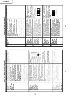
1
SUB-TINT
(I
2
C BUS
CONTROL)
1
.
Select the sub-tint adjustment mode (automatic
Y cut) to receive NTSC colour bar signal.
2.
Connect the oscilloscope to
TP801.
Range
: 20mV/Div (AC)
(Use Probe 10:1)
Sweep
time
: 20µ sec/Div
3.
V
ary the sub tint data to adjust the waveform
to be gained as shown in
Fig 8
.
TP801………………(KY) 6 pin
NTSC CHROMA
ADJUSTMENT
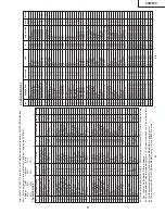
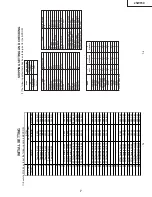
MAIN SCREEN
ADJUSTMENT
V
-AMP
50
Adjust the overscan to 8.5%.(Monoscope)(E-5)
V
-LINE 50
Adjust the linearity to the best. (E-5)
V S-CORR 50
Already preset. (Adjust this unless the linearity
is achieved.) (E-2)
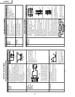
V
-CENT 50
Align the center of the screen to the geometric
center of CR
T
. (E-5)
H-CENT 50
Align the center of the screen to the geometric
center of CR
T
. (E-5)
H-SIZE 50
Adjust the overscan to 8.5% ± 0.5%. (E-5)
E/W
-P
AR 50
Adjust the 2nd vertical line from the left end of
crosshatch pattern so that the midddle 4 blocks
are straight.(E-2) (Refer to Fig.6-1)
E/W
-COR 50
Adjust the 2nd vertical line from the left end of
crosshatch pattern so that the top are straight.(E-
2) (Refer to Fig.6-2)
TRAPE 50
Adjust the 2nd vertical line from the left end of
crosshatch pattern so that the D1 (center area
of the first vertical line-edge of screen) and D2
(top area of the first vertical line-edge of the
screen) are same. (E-2) (Refer to Fig.6-3)
V
-ENT
Already preset.
H-ENT
Already preset.
OTHER
On the items of V
-AMP
60, V
-LINE 60, V S-CORR
60, V
-CENT 60, H-CENT
60, H-SIZE 60, E/W
-
P
AR 60, E/W
-COR 60 and
TRAPE 60, the
compensation data is automatically input if the
50Hz mode adjusutment is done.
Do not change 50Hz mode data after adjust 60Hz
mode data.Because 60Hz mode data follow
50Hz mode data automatically
.
I
2
C BUS
AD-
JUSTMENT
The receiving channel in ( ) are
following signals.
(E-2):Crosshatch(50Hz)
(E-5):Monoscope(50Hz)
Fig. 6-1
Fig. 6-3
However
, if it is largely deviated
when it is checked in 60Hz mode,
readjust it in the 60Hz mode.
Fig. 7
Fig. 8
Cy
G
B
75% W
YM
g
R
100% W
Fig. 6-2
A=B=C
(B-Y)
W
Y
Cy G Mg R B
A
B
C
D2
D1
Summary of Contents for 25WF30
Page 18: ...6 5 4 3 2 1 A B C D E F G H 18 25WF30 CHASSIS LAYOUT ...
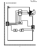
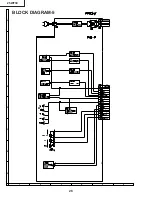
Page 19: ...6 5 4 3 2 1 A B C D E F G H 19 25WF30 BLOCK DIAGRAM 1 ...
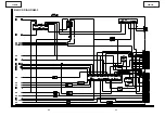
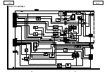
Page 23: ...6 5 4 3 2 1 A B C D E F G H 26 25WF30 BLOCK DIAGRAM 5 ...
Page 26: ...6 5 4 3 2 1 A B C D E F G H 29 25WF30 SCHEMATIC DIAGRAM CRT Unit ...
Page 30: ...6 5 4 3 2 1 A B C D E F G H 36 25WF30 SCHEMATIC DIAGRAM OPERATION Unit ...
Page 35: ...6 5 4 3 2 1 A B C D E F G H 44 25WF30 PWB D OPERATION Unit Wiring Side ...