background image

Ref. No.

Part No.

Description

Code

Ref. No.

Part No.

Description

Code

42

14EM4RU
21EM4RU

D1001 RH-PX0013PEZZ

R PhotoDiode

AC

D1003 VHD1SS119//-1

R 1SS119

AA

D1004 VHD1SS119//-1

R 1SS119

AA

D1007 RH-EX0263TAZZ

R Zener Diode, 8.3V

AB

D1012 RH-EX0611GEZZ

R Zener Diode, 5.1V

AA

D1018 RH-EX0263TAZZ

R Zener Diode, 8.3V

AB

D1019 RH-EX0263TAZZ

R Zener Diode, 8.3V

AB

D1024 VHD1SS119//-1

R 1SS119

AA

PACKAGED CIRCUITS

VA701 RH-VX0073CEZZ

R Varistor

AD

PR701 RMPTP0001PEZZ

R Packaged Circuit

AN

(21EM4RU)

PR702 RMPTP0028CEZZ

R Packaged Circuit

AG

(14EM4RU)

X1001 RCRSB0300CEZZ

R Crystal, 12MHz

AF

COILS AND TRANSFORMER

CF251 RFiLC0318CEZZ

R Filter, 5.5/6MHz

AG

CF252 RFiLC0465CEZZ

R Filter, 6.5MHz

AD

L202

VP-DF270K0000

R Peaking 27

µ

H

AB

L203

VP-DF270K0000

R Peaking 27

µ

H

AB

L204

VP-XF1R2K0000

R Peaking 1.2

µ

H

AB

L251

VP-XF100K0000

R Peaking 10

µ

H

AB

L252

VP-XF6R8K0000

R Peaking 6.8

µ

H

AB

å

L701

RCiLF0086PEZZ

R Coil

AH

L751

RCiLP0225CEZZ

R Coil

AF

L802

VP-DF100K0000

R Peaking 10

µ

H

AB

L803

VP-DF100K0000

R Peaking 10

µ

H

AB

L1030 VP-DF100K0000

R Peaking 10

µ

H

AB

L1050 VP-DF100K0000

R Peaking 10

µ

H

AB

L1051 VP-DF100K0000

R Peaking 10

µ

H

AB

SF201 RFiLC0442CEZZ

R Filter

AL

å

T601

RTRNZ0144PEZZ

R Transformer

AE

å

T602

RTRNF0229PEZZ

R H-Volt Transformer

AY

(21EM4RU)

å

T602

RTRNF0230PEZZ

R H-Volt Transformer

AW

(14EM4RU)

å

T701

RTRNW0015PEZZ

R Transformer

AL

CAPACITORS

C201

VCEA0A R 47

16V Electrolytic

AB

C202

VCEA0A R 330

10V Electrolytic

AC

C203

VCKYCY1HF103Z

R 0.01

50V Ceramic

AA

C204

VCEA0A R 470

6.3V Electrolytic

AC

C205

VCKYCY1HF103Z

R 0.01

50V Ceramic

AA

C206

VCEA0A R 10

50V Electrolytic

AB

C207

VCKYCY1HF103Z

R 0.01

50V Ceramic

AA

C208

VCKYCY1HF103Z

R 0.01

50V Ceramic

AA

C209

VCKYCY1HF103Z

R 0.01

50V Ceramic

AA

C210

VCKYCY1HF103Z

R 0.01

50V Ceramic

AA

C231

VCKYCY1HF223ZY R 0.022 50V Ceramic

AB

C232

VCKYCY1HB821K

R 820p

50V Ceramic

AA

C233

VCKYCY1HB472K

R 4700p 50V Ceramic

AA

C234

VCKYCY1EF104Z

R 0.1

25V Ceramic

AA

C251

VCKYCY1HF223ZY R 0.022 50V Ceramic

AB

C252

VCEA0A R 100

16V Electrolytic

AC

C301

VCEA0A R 470

16V Electrolytic

AC

C304

VCEA0A R 10

16V Electrolytic

AB

C306

VCEA0A R 10

16V Electrolytic

AB

C310

VCEA0A R 1

50V Electrolytic

AB

C311

VCEA0A R 1

50V Electrolytic

AB

C312

VCEA0A R 0.22

50V Electrolytic

AB

C316

VCEA0A R 100

16V Electrolytic

AC

C331

VCKYPA R 1000p 500V Ceramic

AA

C332

VCQYTA R 0.01

50V Mylar

AB

C333

VCEA0A1CW108M

R 1000

16V Electrolytic

AD

C352

VCEA0A R 1

50V Electrolytic

AB

C354

VCEA0A R 1

50V Electrolytic

AB

C356

VCKYCY1HB472K

R 4700p 50V Ceramic

AA

C359

VCEA0A R 10

16V Electrolytic

AB

C360

VCE9GA R 2.2

50V Elect.(N,P)

AB

C409

VCKYCY1CF474Z

R 0.47

16V Ceramic

AB

C410

VCKYCY1CF474Z

R 0.47

16V Ceramic

AB

C411

VCKYCY1HB102K

R 1000p 50V Ceramic

AA

C412

VCEA0A R 470

16V Electrolytic

AC

C501

VCKYPA R 1000p 50V Ceramic

AA

C504

VCKYCY1HB103K

R 0.01

50V Ceramic

AA

C505

VCEA0A R 100

50V Electrolytic

AB

C507

VCKYCY1HB103K

R 0.01

50V Ceramic

AA

C508

VCFYSA

R 0.22

63V

AD

C509

VCEA0A R 470

16V Electrolytic

AC

C510

VCKYPA R 1000p 500V Ceramic

AA

C514

VCFYSA

R 0.056 63V

AD

(14EM4RU)

C514

VCFYSA

R 0.047 63V

AC

(21EM4RU)

C529

VCKYCY1CB823K

R 0.082 16V Ceramic

AH

C531

VCKYCY1HB102K

R 1000p 50V Ceramic

AA

C532

VCKYCY1HB102K

R 1000p 50V Ceramic

AA

C533

VCQYTA R 0.1

50V Mylar

AB

C601

VCQYTA R 0.056 50V Mylar

AB

C602

VCEA0A R 4.7

50V Electrolytic

AB

C603

VCEA0A R 1

50V Electrolytic

AB

C604

VCEA0A2EW106M

R 10

250V Electrolytic

AD

C605

VCKYPA R 1000p 500V Ceramic

AA

C606

VCFPFA2EB334J

R 0.33

250V M.Polypro

AD

(14EM4RU)

C606

VCFPVC2DB474J

R 0.47

200V M.Polypro

AE

(21EM4RU)

C607

VCFPVC3ZA532H

R 5300p 1.8kVM.Polypro

AD

(14EM4RU)

C607

VCFPVC3CA802H

R 8000p 1.6kVM.Polypro

AD

(21EM4RU)

C608

VCKYPA R 1000p 500V Ceramic

AA

C610

VCEA0A1CW108M

R 1000

16V Electrolytic

AD

C611

VCEA0A R 47

25V Electrolytic

AB

C612

VCEA0A R 470

16V Electrolytic

AC

C620

VCKYPA R 1000p 500V Ceramic

AA

å

C640

VCFYSB2EB823J

R 0.082 250V

AD

C651

VCQYTA R 2200p 50V Mylar

AA

C652

VCQYTA R 4700p 50V Mylar

AB

C653

VCEA0A R 1

50V Electrolytic

AB

C654

VCKYCY1HF223ZY R 0.022 50V Ceramic

AB

C655

VCEA0A R 10

50V Electrolytic

AB

C656

VCEA0A R 0.47

50V Electrolytic

AB

C657

VCKYCY1EF104Z

R 0.1

25V Ceramic

AA

C658

VCKYCY1EF104Z

R 0.1

25V Ceramic

AA

C701

RC-FZ031SCEZZ

R 0.1

275V

AD

C702

RC-KZ0

R 0.01

250V Ceramic

AC

C703

RC-KZ0

R 0.01

250V Ceramic

AC

C704

RC-KZ0

R 0.01

250V Ceramic

AC

C705

RC-EZA096WJZZ

R 2200

400V Electrolytic

AL

 (14EM4RU)

C705

RC-EZA097WJZZ

R 2200

400V Electrolytic

AM

(21EM4RU)

C709

RC-KZ0039CEZZ

R 680p

2kV Ceramic

AB

C710

VCEA0A R 47

50V Electrolytic

AB

C711

VCKYPA R 1000p 50V Ceramic

AA

C712

VCKYPA R 470p

50V Ceramic

AA

å

C751

RC-KZ0106GEZZ

R 3300p AC250VCeramic

AG

C752

VCKYPH3DB561K

R 560p

2kV Ceramic

AC

C753

RC-EZ0776CEZZ

R 100

160V Electrolytic

AF

C754

RC-EZA069WJZZ

R 33

160

Electrolytic

AE

C755

VCEA0A1CW108M

R 1000

16V Electrolytic

AD

C756

VCQYTA R 0.01

50V Mylar

AB

C759

VCEA0A R 470

6.3V Electrolytic

AC

C760

VCEA0A0JW228M

R 2200

6.3V Electrolytic

AD

C801

VCEA0A R 1

50V Electrolytic

AB

C803

VCEA0A R 100

16V Electrolytic

AC

C804

VCKYCY1HB222K

R 2200p 50V Ceramic

AA

C805

VCKYD41HB102K

R 1000p 50V Ceramic

AA

C806

VCKYD41HB102K

R 1000p 50V Ceramic

AA

C807

VCKYD41HB102K

R 1000p 50V Ceramic

AA

C808

VCEA0A R 100

16V Electrolytic

AC

C809

VCKYCY1CF474Z

R 0.47

16V Ceramic

AB

C810

VCKYCY1CF474Z

R 0.47

16V Ceramic

AB

C811

VCEA0A R 100

16V Electrolytic

AC

C812

VCFYFA

R 0.22

50V Mylar

AB

C813

VCFYFA

R 0.22

50V Mylar

AB

C814

VCKYCY1HB471K

R 470p

50V Ceramic

AB

C816

VCKYCY1HB471K

R 470p

50V Ceramic

AB

C1001 VCEA0A R 100

6.3V Electrolytic

AB

Summary of Contents for 14EM4RU

Page 1: ...uner Ë AVL Sound Keeper Function Ë Black Stretch Circuit Ë On Timer Off Timer Reminder Timer Ë Blue Back Noise Mute Ë Front Headphone Terminal Ë Front AV In Rear AV In Out Terminals Front Priority Ë Colour Comb Filter NTSC AV THRU only Ë High Contrast Picture Ë Hotel Mode Ë English Russian 2 Languages OSD Ë White Temperature Adjustment 14EM4RU 21EM4RU Page CONTENTS Page SPECIFICATIONS 2 IMPORTANT ...

Page 2: ...safety 3 Do not lift picture tube by the neck 4 Handle the picture tube only when wearing shatterproof goggles and after discharging the high voltage completely X RAY This receiver is designed so that any X Ray radiation is kept to an absolute Minimum Since certain malfunctions or servicing may produce potentially hazardous radiation with prolonged exposure at close range the following precautions...

Page 3: ...he chassis has been assembly together and ready to be POWER ON for the FIRST TIME make sure to short JA137 JA138 to switch to the service mode position first and then turn on the main power switch See 2 1 above Precaution If haven t done this initiation it may possibly generate excessive Beam current 3 For reference please check with memory map GA 1A Series type RH IX3368CE Attachment SERVICE MODE...

Page 4: ...F NTSC 3 58 F N358 FE RF NTSC 4 43 F N443 FE RF SECAM F SECAM VIDEO MUTE AT IDENT LOSS VMI VIDEO MUTE AT PROGRAM SOURCE CHANGE VMC HOTEL MODE HTL REDUCED FM DEMODULATION GAIN FOR BTSC SIGNAL BTSC A A NUMBER OF EXT AV SOURCE AV FM WINDOW SELECTION FMWS SOUND MUTE BIT 0 SM0 SOUND MUTE BIT 1 SM1 THAI LANGUAGE THA ARABIC LANGUAGE ARA MALAY LANGUAGE MAL CHINESE LANGUAGE CHI FRENCH LANGUAGE FRE RUSSIAN ...

Page 5: ... 43H 01H 4FH 03H A1H EEPROM ITEMS OSD DATA LENGTH INITIAL DATA FIX ADJ REMARK SHARPNESS OFFSET NTSC443 SHP O4 0 15 8 FIX VERTICAL SCAN DISABLE VSD 0 DISABLE 1 ENABLE 0 FIX BLACK STRETCH BKS 0 DISABLE 1 ENABLE 1 FIX AUTOMATIC VOLUME LEVELING AVL 0 DISABLE 1 ENABLE 1 FIX FAST FILTER IF PLL FFI 0 DISABLE 1 ENABLE 0 FIX ENABLE VERTICAL GUARD RGB BLANKING EVG 0 DISABLE 1 ENABLE 1 FIX EHT TRACKING MODE ...

Page 6: ... store the following tuning data in E 2 PROM Note All sound system of following channels will be set to B G after pressing INITIAL KEY 2 3 or 4 SHIPPING SETTING CHECKING 1 The following default data has been factory set for the E 2 PROM ITEMS DATA SETTING LAST PROGRAM CHANNEL 1 FLASHBACK PROGARM CH 1 DIGIT 1 C SYSTEM AUTO S SYSTEM 1 SKIP OFF AFC ON VOLUME 1 CONTRAST 60 MAX COLOUR 0 CENTER BRIGHTNE...

Page 7: ... of using impedance adapter 2 Fig 3 Fig 1 Fig 2 Bias box About 4 5 V Oscilloscope 0 1V TV Set Bias box TP210 E 9 CH P C 10k 100k 1n60 75ohm IF OUT 1 5 0 8dB 1000p Oscilloscope ADJUSTMENT PRECAUTION Make sure TV Set is in Normal Condition before switch to service mode for adjust ment PURITY ADJUSTMENT No Adjusting point Adjusting procedure conditions Waveform and others PURITY ADJ 1 Receive the GRE...

Page 8: ... AKB start function 5 Then continue adjust until retrace line appear 6 Finally slowly decrease the screen variable re sistor until screen retrace line cut off Not Raster Note Must confirm the AKB function in set before con tinue the next adjustment 1 SUB BRIGHT NESS ADJUSMENT I 2 C BUS CONTROL 1 Call SUB BRI in service mode Receive Cross hatch pattern with 5 black level windows 2 Adjust the SUB BR...

Page 9: ... the Monoscope Pattern signal 2 Press R C to set Picture NORMAL condition 3 Connect the DC miliammeter between TP603 TP602 Full Scale 3 mA Range 4 Beam current must be within 800 100 µA 14 1 100 100 µA 21 4 6 No Adjusting point Adjusting procedure conditions Waveform and others SUB TINT I 2 C BUS CON TROL 1 Receive the NTSC 3 58 Colour Bar signal thru AV in 2 Connect the oscilloscope to TP47B P882...

Page 10: ...splay of the channel number in green colour under AFT ON condition 6 FUNCTION OPERATION CHECKING VIDEO AND AUDIO Continued No Adjusting point Adjusting procedure conditions Waveform and others COLOUR SYSTEM 1 Receive the PAL COLOUR BAR signal press the COLOUR SYSTEM key to select modes ex cept PAL check the COLOUR is not working prop erly Then select the PAL mode Check again its colour so that it ...

Page 11: ...F 46 SM1 SM0 FMWS AV BTSC HTL VMC VMI 00 FF 47 HP2 FSL RUS FRA CHN MLY ARB THA 00 FF 48 AGC1 AGC0 BIL CPT FOB AV FOA AV FOB FE FOA FE NDF MSA LED F 00 FF 00 03 49 4A 4B 4C VOLUME 01 00 3C 4D CONTRAST 3C 00 3C 4E COLOUR 1E 00 3C 4F BRIGHTNESS 1E 00 3C 50 TINT 1E 00 3C 51 SHARPNESS 1E 00 3C 52 53 54 55 POSITION AV1 AV2 01 00 FF 56 FAV POS A 0A 00 FF 57 FAV POS B 14 00 FF 58 FAV POS C 1E 00 FF 59 FAV...

Page 12: ...S CTV FINAL LAST INITIAL SETTING DATA DEFAULT RANGE WRITE CPU CHECK DATA CHECK TYPE CHECK DATA CHECK TYPE REMARK ADDRESS DATA HEX D7 D6 D5 D4 D3 D2 D1 D0 C0 TUNING FREQUANCY LOWER PART POS 25 C1 S SYS AFT auto C SYS C2 TUNING FREQUANCY HIGHER PART POS 26 C3 TUNING FREQUANCY LOWER PART C4 S SYS AFT auto C SYS C5 TUNING FREQUANCY HIGHER PART POS 27 C6 TUNING FREQUANCY LOWER PART C7 S SYS AFT auto C ...

Page 13: ... CTV FINAL LAST INITIAL SETTING DATA DEFAULT RANGE WRITE CPU CHECK DATA CHECK TYPE CHECK DATA CHECK TYPE REMARK ADDRESS DATA HEX D7 D6 D5 D4 D3 D2 D1 D0 140 TUNING FREQUANCY HIGHER PART POS 68 141 TUNING FREQUANCY LOWER PART 142 S SYS AFT auto C SYS 143 TUNING FREQUANCY HIGHER PART POS 69 144 TUNING FREQUANCY LOWER PART 145 S SYS AFT auto C SYS 146 TUNING FREQUANCY HIGHER PART POS 70 147 TUNING FR...

Page 14: ... auto C SYS 19A TUNING FREQUANCY HIGHER PART POS 98 19B TUNING FREQUANCY LOWER PART 19C S SYS AFT auto C SYS 19D TUNING FREQUANCY HIGHER PART POS 99 19E TUNING FREQUANCY LOWER PART 19F S SYS AFT auto C SYS 1A0 AV1 1A1 1A2 auto C SYS 1A3 AV2 1A4 1A5 auto C SYS 1A6 1A7 1A8 1A9 1AA 1AB 1AC 1AD 1AE 1AF 1B0 1B1 1B2 1B3 1B4 1B5 1B6 1B7 1B8 1B9 1BA 1BB 1BC 1BD 1BE 1BF MODEL MODEL LETTER NO LETTER NO TUNI...

Page 15: ... circuit oscillate Check Q752 and IC801 D1001 Power LED Red dimly turns on or turns ON OFF Check T701 pin 11 voltage Approx 310V at 220V AC Check F701 Check Secondary Main B Approx 130V Check CRT connector K1 K5 bias Check C878 Check IC801 Checking the protector circuit Check R618 and R619 D1001 Power LED Red brightly turns on Check D751 Check R701 and R707 ...

Page 16: ...nd related circuit Check pin 38 of IC801 Does the noise level increase at max Contrast Brightness and Sound controls CIRCUITS TO BE CHECKED Tuner PIF Automatic Gain Control 5V 32V Power Source CIRCUITS TO BE CHECKED Sound system pins 28 29 and 44 of IC801 Sound Detector Circuit Sound Switch and Att Control Audio Output Circuit Does signal appear at pins 2 and 4 of IC302 Check P302 P303 connector o...

Page 17: ...agenta The picture colour is cyan Check Q871 Q883 and their adjacent circuits for 14 Check Q870 Q885 and their adjacent circuits for 21 Check Q870 Q885 and their adjacent circuits for 14 Check Q871 Q883 and their adjacent circuits for 21 Check Q872 Q887 and their adjacent circuits for 14 21 Check IC801 and bias control circuit NO SPECIFIC COLOUR PAL SECAM NO COLOUR SYNCHRONIZATION Check IC801 R801...

Page 18: ...10 Vp p H 4 3 10 Vp p H 2 3 00 Vp p H 8 3 2 Vp p H 9 2 32 Vp p H 10 122 Vp p H 7 79 2 Vp p H 11 8 8 Vp p H 13 110 Vp p H 14 1100Vp p H 15 480 Vp p H 12 50 Vp p H 16 28 Vp p H 17 2 08 Vp p H WAVEFORMS 14EM4RU 6 78 4 Vp p H 5 70 0 Vp p H ...

Page 19: ... 8 Vp p 6 90 4 Vp p 1 1 04 Vp p 3 3 40 Vp p 4 3 12 Vp p 2 3 32 Vp p 8 3 16 Vp p 9 2 44 Vp p 10 122 Vp p 7 88 6 Vp p 11 8 72 Vp p 13 140 Vp p 14 1200kVp p 15 528 Vp p 12 47 2 Vp p 16 27 2 Vp p V 17 2 00 Vp p WAVEFORMS 21EM4RU ...

Page 20: ... 1 64 33 4 TX0110BM TX0124BM 2SC3198 2SC3207 DX0111PE BASE COLLECTOR EMITTER BASE COLLECTOR EMITTER B C E KA7808A 1 2 3 CATHODE ANODE RED STRG5653 AN7523 PX0013PE 2SD2586 1 9 ZR BR COLLECTOR COLLECTOR BASE EMITTER BASE EMITTER IX3368CE 1 32 AN5522 14 STV9302A 21 1 2 3 4 5 6 7 SIDE VIEW ...

Page 21: ...21 14EM4RU 21EM4RU MODEL 14EM4RU CHASSIS LAYOUT ...

Page 22: ...22 14EM4RU 21EM4RU MODEL 21EM4RU CHASSIS LAYOUT ...

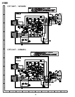
Page 23: ...23 14EM4RU 21EM4RU BLOCK DIAGRAM CRT UNIT BLOCK DIAGRAM 14EM4RU CRT UNIT BLOCK DIAGRAM 21EM4RU ...

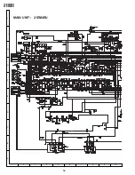
Page 24: ...24 14EM4RU 21EM4RU BLOCK DIAGRAM MAIN UNIT 14EM4RU ...

Page 25: ...25 14EM4RU 21EM4RU ...

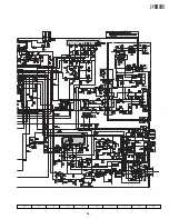
Page 26: ...26 14EM4RU 21EM4RU BLOCK DIAGRAM MAIN UNIT 21EM4RU ...

Page 27: ...27 14EM4RU 21EM4RU ...

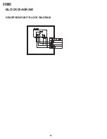
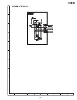
Page 28: ...28 14EM4RU 21EM4RU BLOCK DIAGRAM HEADPHONE UNIT BLOCK DIAGRAM ...

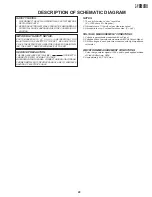
Page 29: ...NNECTED WITH AC MAINS VOLTAGE WHEN SERVICING THE AREA CONNECT AN ISOLATING TRANS FORMER BETWEEN TV RECEIVER AND AC LINE TO ELIMINATE HAZARD OF ELECTRIC SHOCK NOTES 1 The unit of resistance ohm is omitted K 1000 ohms M Meg ohm 2 All resistors are 1 16 watt unless otherwise noted 3 All capacitors are µF unless therwise noted P µµF VOLTAGE MEASUREMENT CONDITIONS 1 Voltage in parenthesis measured with...

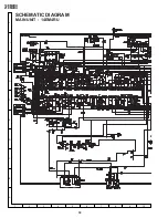
Page 30: ...30 14EM4RU 21EM4RU A B C D E F G H I J 1 2 3 4 5 6 7 8 9 10 MAIN UNIT 14EM4RU SCHEMATIC DIAGRAM ...

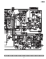
Page 31: ...31 14EM4RU 21EM4RU 10 11 12 13 14 15 16 17 18 19 ...

Page 32: ...32 14EM4RU 21EM4RU MAIN UNIT 21EM4RU A B C D E F G H I J 1 2 3 4 5 6 7 8 9 10 ...

Page 33: ...33 14EM4RU 21EM4RU 10 11 12 13 14 15 16 17 18 19 ...

Page 34: ...34 14EM4RU 21EM4RU A B C D E F G H I J 1 2 3 4 5 6 7 8 9 10 CRT UNIT 14EM4RU CRT UNIT 21EM4RU ...

Page 35: ...35 14EM4RU 21EM4RU A B C D E F G H I J 1 2 3 4 5 6 7 8 9 10 HEADPHONE UNIT ...

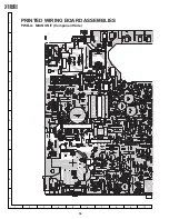
Page 36: ...36 14EM4RU 21EM4RU A B C D E F G H I J 1 2 3 4 5 6 7 8 9 10 PRINTED WIRING BOARD ASSEMBLIES PWB A MAIN UNIT Component Side ...

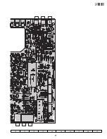
Page 37: ...37 14EM4RU 21EM4RU 10 11 12 13 14 15 16 17 18 19 ...

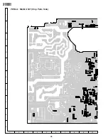
Page 38: ...38 14EM4RU 21EM4RU PWB A MAIN UNIT Chip Parts Side A B C D E F G H I J 1 2 3 4 5 6 7 8 9 10 ...

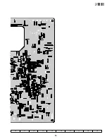
Page 39: ...39 14EM4RU 21EM4RU 10 11 12 13 14 15 16 17 18 19 ...

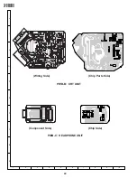
Page 40: ...40 14EM4RU 21EM4RU A B C D E F G H I J 1 2 3 4 5 6 7 8 9 10 Wiring Side PWB B CRT UNIT Chip Parts Side PWB C HEADPHONE UNIT Component Side Chip Side ...

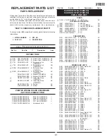
Page 41: ...R KIA7808API AE IC701 VHiSTRG5653 1 R STR G5653 AQ IC801 RH iX3368CEN6 R I C BE IC1005 VHiCAT24W04 1 R I C AE TRANSISTORS Q201 VS2SC2735 1E R 2SC2735 AC Q251 VS2PD601AR 1 R 2PD601AR AB Q252 VS2SC3198 G 1 R 2SC3198 G AA Q302 VS2PD601AR 1 R 2PD601AR AB Q321 VS2PD601AR 1 R 2PD601AR AB Q352 VS2PD601AR 1 R 2PD601AR AB Q501 VS2SC3198 G 1 R 2SC3198 G AA Q601 VS2SC3207 1 R 2SC3207 AC Q602 VS2SD2586 1E R 2...

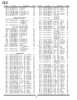
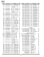
Page 42: ...470 16V Electrolytic AC C501 VCKYPA1HB102K R 1000p 50V Ceramic AA C504 VCKYCY1HB103K R 0 01 50V Ceramic AA C505 VCEA0A1HW107M R 100 50V Electrolytic AB C507 VCKYCY1HB103K R 0 01 50V Ceramic AA C508 VCFYSA1JB224J R 0 22 63V AD C509 VCEA0A1CW477M R 470 16V Electrolytic AC C510 VCKYPA2HB102K R 1000p 500V Ceramic AA C514 VCFYSA1JB563J R 0 056 63V AD 14EM4RU C514 VCFYSA1JB473J R 0 047 63V AC 21EM4RU C5...

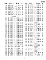
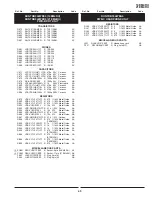
Page 43: ...xide AA R234 VRS CY1JF391J R 390 1 16W Metal Oxide AA R251 VRS CY1JF181J R 180 1 16W Metal Oxide AA R252 VRS CY1JF181J R 180 1 16W Metal Oxide AA R253 VRD RA2BE680J R 68 1 8W Carbon AA R254 VRS CY1JF560JY R 56 1 16W Metal Oxide AA R255 VRS CY1JF223J R 22k 1 16W Metal Oxide AA R256 VRS CY1JF223J R 22k 1 16W Metal Oxide AA R262 VRS CY1JF560JY R 56 1 16W Metal Oxide AA R263 VRS CY1JF560JY R 56 1 16W ...

Page 44: ...IC501 AD RDA602 PRDAR0224PEFW R Heat Sink for Q602 AF 21EM4RU RDA701 PRDAR0298PEFW R Heat Sink for IC701 AF TP201 QLUGP0102PEZZ R Lug AA QCNW A291WJZZ R Connecting Cord AD QCNW A292WJZZ R Connecting Cord AD LHLDP1066PE00 R Holder AC R612 VRS CY1JF123J R 12k 1 16W Metal Oxide AA R613 VRS CY1JF103J R 10k 1 16W Metal Oxide AA R614 VRS VU2HE100J R 10 1 2W Metal Oxide AA 21EM4RU R614 VRS VU2HE150J R 15...

Page 45: ... CY1JF471J R 470 1 16W Metal Oxide AA R881 VRS CY1JF471J R 470 1 16W Metal Oxide AA R882 VRS VU3DE153J R 15k 2W Metal Oxide AB R883 VRD RM2HD272J R 2 7k 1 2W Carbon AA R884 VRS VU3DE153J R 15k 2W Metal Oxide AB R885 VRD RM2HD272J R 2 7k 1 2W Carbon AA R886 VRS VU3DE153J R 15k 2W Metal Oxide AB R887 VRD RM2HD272J R 2 7k 1 2W Carbon AA R888 VRS CY1JF471J R 470 1 16W Metal Oxide AA 14EM4RU R892 VRS C...

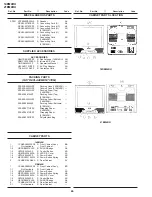
Page 46: ...14EM4RU SPAKX0067KJZZ Packing Foam Top 21EM4RU SPAKXA204WJZZ Packing Foam Bottom 14EM4RU SPAKX0068KJZZ Packing Foam Bottomp 21EM4RU SPAKP0677CEZZ Wrapping Paper 14EM4RU SPAKP0697CEZZ Wrapping Paper 21EM4RU SSAKA0230CEZZ Polyethylene Bag CABINET PARTS 14EM4RU 1 CCABAA284WEA0 R Front Cabinet Ass y BB 1 1 Not Available Front Cabinet 1 2 HBDGB0001KJSC R SHARP Badge AE 1 3 JBTN 0043KJSF R Control Butto...

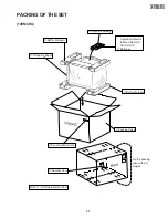
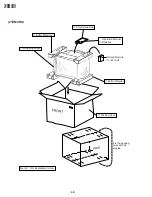
Page 47: ...14EM4RU 21EM4RU PACKING OF THE SET 14EM4RU Polystyrene Bag Operation Manual Infrared Remote Control Unit Batteries Buffer Material Packing Case Fix the packing case with 22 staples Number Card Wrapping Paper Mark Not Replacement Item Buffer Material Serial Number Card ...

Page 48: ... 21EM4RU Polystyrene Bag Operation Manual Batteries Infrared Remote Control Unit Buffer Material Packing Case Fix the packing case with 22 staples Wrapping Paper Mark Not Replacement Item Buffer Material 21EM4RU ...

Page 49: ...49 14EM4RU 21EM4RU ...

Page 50: ...tted in any form or by any means electronic mechanical photocopying recording or otherwise without prior written permission of the publisher SHARP CORPORATION AV Systems Group Quality Reliability Control Center Yaita Tochigi 329 2193 Japan TQ1553 S May 2003 Printed in Japan In Japan gedruckt MY DS Design and Production Information Design SEM Production SREC ...

Reviews: