16
16-1
16-2
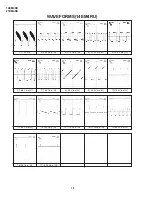
14EM4RU
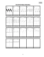
21EM4RU
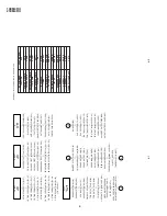
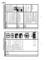
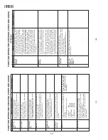
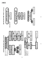
TROUBLE SHOOTING TABLE
(Continued)
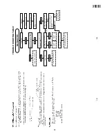
NO PICTURE, NO SOUND
Does noise signal appear at
pin (44) of IC801 ?
NO SOUND
No snow noise.
Does noise or signal appear at pin (40)
of IC801 ?
Noise increases but no signal is
received.
Check the tuner supply voltage LB must
be approx. 5V. BT must be approx, 32V.
And CH preset data check.
Check the tuner AGC
(TP201).
Does noise or
signal appear at
pin (38) of IC801 ?
Check IC801 and
its related circuit.
Does noise or
signal appear at
pins (23) and
(24)of IC801.
Check Q251, Q252
and related circuit.
Check pin (37)of
IC801 and related
circuit.
Check pin (1) of
SF201 and Tuner
related circuit.
Check IC801.
Check C356,
C359 and
peripheral circuit.
Check pin (27) of
IC801, Tuner and
related circuit.
Check pin(38) of
IC801.
Does the noise level increase at max.
Contrast, Brightness and Sound controls ?
CIRCUITS TO BE CHECKED:
»
Tuner.
»
PIF.
»
Automatic Gain Control.
»
(5V), (32V) Power Source.
CIRCUITS TO BE CHECKED:
»
Sound system pins (28), (29)
and (44) of IC801.
»
Sound Detector Circuit.
»
Sound Switch and Att.
Control.
»
Audio Output Circuit.
Does signal appear at pins
(2) and (4) of IC302 ?
Check P302,P303 connector
of IC302 and peripheral
circuit.
Check Q321, pins(4) and (6)
of IC801 and peripheral
circuit.
Does signal appear at pins(28)
and (29) of IC801?
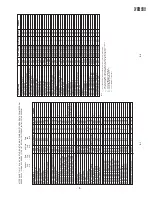
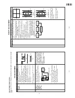
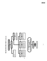
TROUBLE SHOOTING TABLE
(Continued)
NEITHER VERTICAL NOR
HORIZONTAL SYNCHRONIZATION
CIRCUIT TO BE CHECKED:
»
Sync. Separator Circuit.
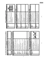
NO VERTICAL SCAN
Vertical linearity and size is
abnormal.
Check pins(33) and (34) of
IC801.
DEFECTIVE VERTICAL AMP.
AND VERTICAL LINEARITY
Readjust vertical size.
(Bas Data)
Check IC501.
Check C505 and C509.
Check IC501.
Check R501, R503, R512,
R521, R533 and C533.
Summary of Contents for 14EM4RU
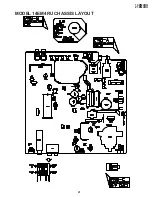
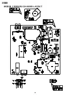
Page 21: ...21 14EM4RU 21EM4RU MODEL 14EM4RU CHASSIS LAYOUT ...
Page 22: ...22 14EM4RU 21EM4RU MODEL 21EM4RU CHASSIS LAYOUT ...
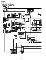
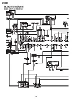
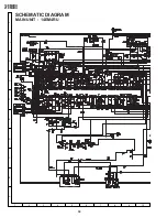
Page 24: ...24 14EM4RU 21EM4RU BLOCK DIAGRAM MAIN UNIT 14EM4RU ...
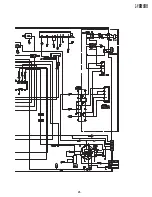
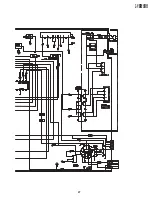
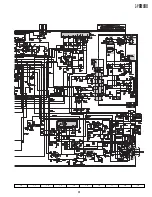
Page 25: ...25 14EM4RU 21EM4RU ...
Page 26: ...26 14EM4RU 21EM4RU BLOCK DIAGRAM MAIN UNIT 21EM4RU ...
Page 27: ...27 14EM4RU 21EM4RU ...
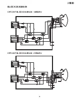
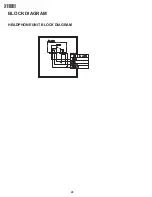
Page 28: ...28 14EM4RU 21EM4RU BLOCK DIAGRAM HEADPHONE UNIT BLOCK DIAGRAM ...
Page 31: ...31 14EM4RU 21EM4RU 10 11 12 13 14 15 16 17 18 19 ...
Page 32: ...32 14EM4RU 21EM4RU MAIN UNIT 21EM4RU A B C D E F G H I J 1 2 3 4 5 6 7 8 9 10 ...
Page 33: ...33 14EM4RU 21EM4RU 10 11 12 13 14 15 16 17 18 19 ...
Page 34: ...34 14EM4RU 21EM4RU A B C D E F G H I J 1 2 3 4 5 6 7 8 9 10 CRT UNIT 14EM4RU CRT UNIT 21EM4RU ...
Page 35: ...35 14EM4RU 21EM4RU A B C D E F G H I J 1 2 3 4 5 6 7 8 9 10 HEADPHONE UNIT ...
Page 37: ...37 14EM4RU 21EM4RU 10 11 12 13 14 15 16 17 18 19 ...
Page 38: ...38 14EM4RU 21EM4RU PWB A MAIN UNIT Chip Parts Side A B C D E F G H I J 1 2 3 4 5 6 7 8 9 10 ...
Page 39: ...39 14EM4RU 21EM4RU 10 11 12 13 14 15 16 17 18 19 ...
Page 49: ...49 14EM4RU 21EM4RU ...

