


8
HNG SERIES PRESSURE WASHER
OPERATOR’S MANUAL
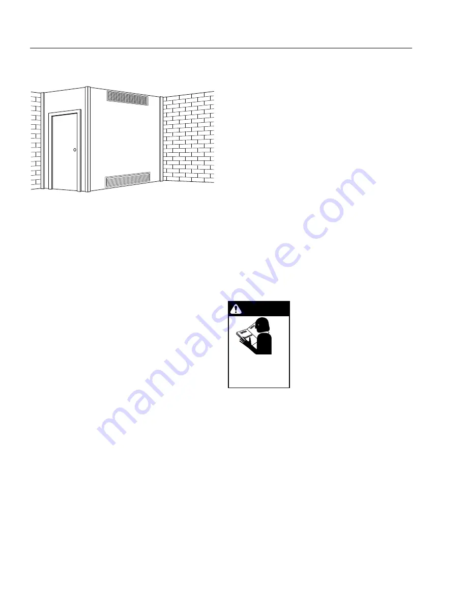
Figure 4
Ventilating Air Opening.
1 square inch for each
1000 BTU per hour input.
Illustration showing air openings necessary
to supply air for combustion when installed
in an enclosed room.
Water Source:
The water source for the machine should be supplied by
a 5/8" I.D. garden hose with a city water pressure of not
less than 30 PSI. If the water supply is inadequate, or if
the garden hose is kinked, the machine will run very rough
and the burner will not fire.
Water Connection:
Connect the high pressure hose by pulling the coupler
collar back and then inserting it onto the discharge nipple.
Secure it by pushing the collar forward.
Attach the wand into the spray gun using teflon tape on
the pipe threads to avoid leaks.
Inspection and Testing Gas Piping:
The building structure should not be weakened by in-
stalling the gas piping. The piping should not be sup-
ported by other piping, but should be firmly supported
with gas hooks, straps, bands or hangers. Butt or lap
welded pipe should not be run through or in an air duct
or clothes chute.
Before turning gas under pressure into piping, all open-
ings from which gas can escape should be closed. Im-
mediately after turning on gas, the system should be
checked for leaks. This can be done by watching the 1/2
cubic foot test dial for 5 minutes for any movement or by
soaping each pipe connection and watching for bubbles.
If a leak is found, make the necessary repairs and re-
peat the above test.
Defective pipes or fittings should be replaced and not
repaired. Never use a flame or fire in any form to locate
gas leaks — use a soap solution.
After the piping and meter have been checked completely,
purge the system of air.
DO NOT
bleed the air inside an
enclosed room.
During pressure testing of the system at test pressures
in excess of 1/2 PSIG, the appliance and its individual
shut-off valve must be disconnected from the gas sup-
ply piping system or damage to the gas valve will occur.
Gas Pressure:
The ideal incoming gas pressure is 11 water column
inches or w.c.i. (minimum 9 w.c.i, maximum 14 w.c.i. or
1/2 PSIG). The correct operating manifold pressure for
natural gas is 3.5 w.c.i. The operating manifold pressure
for propane gas is 10 w.c.i. By adjusting the gas valve
pressure regulator between 3 and 4 w.c.i. a side range
can be achieved for natural gas.
If the desired input rating cannot be obtained within the
above manifold pressure adjusting range, then the next
size larger or smaller burner orifice should be used.
START-UP
WARNING: Read and follow in-
structions carefully when install-
ing or servicing machine. Failure
to do so may result in damage to
property or personal injury.
1. Installation or servicing of gas
appliances and controls must
only be performed by qualified
personnel. After installation or
servicing, test manual valve,
operating valves, pressure regulation, and automatic
shut-off valve for proper operation.
2. Install in a suitable dry location. The machine must
be located in an area properly protected from the
weather.
3. Shut off gas and electricity before starting installa-
tion or service. Turn back on to test or operate.
4.
DO NOT
connect appliances before pressure test-
ing the gas piping. Damage to gas valve may result.
(9 - 14 w.c.i. or 1/2 PSIG)
5.
DO NOT
insert any object other than suitable pipe
or tubing in the inlet or outlet of the gas valve. Inter-
nal damage may occur and result in a hazardous
condition.
6.
DO NOT
grip gas valve body with a pipe wrench or
vise. Damage may result causing gas leakage. Use
inlet or outlet bosses or a special body wrench.
7.
DO NOT
short the gas valve terminals.
WARNING
READ
SAFETY
INSTRUCTIONS
PRIOR
TO
INSTALLING
OR
SERVICING
MACHINE
.
Summary of Contents for HNG-3010
Page 35: ......