Shark HNG-3010 Operator'S Manual Download Page 15

HNG SERIES PRESSURE WASHER  

OPERATOR’S MANUAL

15

Gas Pressure Requirements:

All propane fired machines operate on gas phase only.
They are designed to operate at a pressure of 11 w.c.i.
(between 1/3 and 1/2 of one PSI), and are often oper-
ated at even higher pressures when extra heat is needed.

Exterior regulators are needed to control the system. Pro-
pane bottles are not included with the machine. A high
pressure regulator should be installed on the propane
bottle and a low pressure regulator attached to the pres-
sure washer.

Propane Cylinder Capacity:

An important consideration with propane systems is the
capacity of the supply cylinder relative to the needs of
the burner. The burner operates on propane as a gas.
As gas is used from the propane cylinder, the liquid in
the cylinder boils to maintain gas pressure. This boiling
process cools the liquid, and in a heavy, continuous-de-
mand situation, the liquid temperature can fall to the point
at which it cannot provide gas as rapidly as is needed. In
this case, it may be necessary to warm the propane cyl-
inder by directing a warm spray, not over 120°, on the
cold cylinder, or by manifolding two propane bottles to-
gether to increase total vaporization capacity. It is rec-
ommended that a minimum 100 lb. propane bottle be
used on the machine, depending on the length of run-
ning time desired.

BURNER FEATURES

Operated Automatic Valve:

This machine is equipped with a thermopile self-pow-
ered combination gas control. This system is designed
as a constant burning pilot. Lighting of the pilot is ac-
complished by manually lighting the pilot. A thermostat
and flow switch control the main solenoid valve.

Care of Main Burner:

Due to condensation from heater coils dripping down on
the burners, a scale buildup may occur in the burner jet
orifices.

  1.

TO REMOVE BURNER MANIFOLD FROM
WATER HEATER COIL:

Turn off the gas at the main burner by turning the
knob to the “OFF” position on the gas valve and main
gas supply.

Disconnect the pilot and ignition lines from the gas
valve. Disconnect union in main burner line. (Remove
the nuts from the U-bolts, item 28 on page 23).  Slide
burner manifold out through shell opening.

  2.

TO CLEAN BURNER JETS:

Select proper size drill for type of gas involved. Use
vise to hold drill and to ream out each jet orifice.

If the water heater will be exposed to freezing weather,
an antifreeze solution should be circulated through the
coils by whatever means are available for the particular
system the water heater is used on.

BURNER TROUBLESHOOTING

Millivolt System Check:

This machine has a thermopile self-powered combina-
tion gas control. Before checking the millivolt system,
the following operations should be performed and ob-
servations made:

  1. Inspect system for proper wiring.

  2. The switch leads and all wire connections should be

cleaned and tightened to eliminate all unnecessary
resistance.

  3. Clean and/or adjust pilot for maximum flame impinge-

ment on the thermopile.

  4. If pilot will not remain lit when gas cock dial is re-

leased, check automatic pilot (Step D).

The millivolt system and individual components may be
checked with a DC millivolt meter having a 0-1000 MV
range. Conduct each check as shown in the chart below
by connecting the meter test leads to terminals as indi-
cated. All readings are closed circuit.
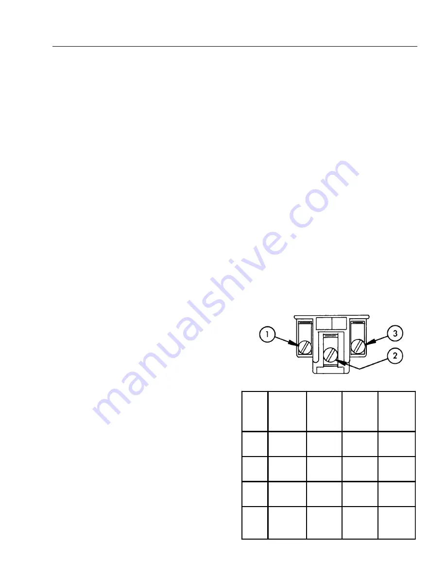
TERM

TERM

TERM

TH
TP

TH

TP

MILLIVOLT


OPERATOR

TERMINAL


PANEL

Check

Test

To Test

Connect

Meter

Leads To

Terminals

Switch

Flow &
Burner

Contacts

Meter

Reading

Should

Be

A

Complete

System

2 & 3

Closed

100 MV or

More

B

Thermopile

Output

1 & 2

Open

Greater

than 250

C

System

Resistance

1 & 3

Closed

Less than

35

D

Auto/Pilot

Dropout

1 & 2

Open

Between

120 - 30

MV

Summary of Contents for HNG-3010

Page 1: ...SHARK PRESSURE WASHERS 4275 N W Pacific Rim Blvd Camas WA 98607 USA For technical assistance or the Shark Dealer nearest you call 1 800 771 1881 OPERATOR S MANUAL HNG 3010 HNG 4020 HNG 3530 HNG LISTED ...

Page 2: ...entification 11 Operating Instructions 12 Preventatative Maintenance 12 General Washing Techniques 12 13 Maintenance Service 13 Heating Coils 13 14 Propane Gas 14 Burner Features 15 BurnerTroubleshooting 15 16 Hose Spray Gun Assembly 17 Exploded View Left Side 18 Exploded View Right Side 19 Exploded View Parts List 20 21 HNG Burner Assembly Exploded View 22 HNG Burner Assembly Exploded View Parts ...

Page 3: ...y with the National Electrical code NFPA 70 and provide additional protection from risk of elec tric shock this pressure washer is equipped with a UL approved ground fault circuit interrupter GFCI power cord for machines rated 250V 30 amp or less single phase 3 Know how to stop the machine and bleed pressures quickly Be thoroughly familiar with the controls 4 Stay alert Watch what you are doing WA...

Page 4: ...unburned gas may be present 23 Never attempt to light pilot unless pilot manual valve has been shut off for 5 minutes 24 A conversion kit as supplied by the manufacturer shall be used to convert natural gas to propane 25 L P gases are heavier than air and will spill out on the floor Therefore always provide adequate space and ventilation around these machines Install machine 18 above the floor 26 ...

Page 5: ...HNG SERIES PRESSUREWASHER OPERATOR S MANUAL 5 INSTALLATION GUIDE HNG 9 57 I D 49 0 38 3 8 High Pressure Out 11 3 4 27 1 2 44 1 4 Gas In 1 1 2 NPT M 3 0 Fresh Water In 1 0 GHF 1 1 4 ...

Page 6: ...Keep all flammable material at least 20 feet away Allow enough space for servicing the machine Local code will require certain distances from floor and walls Two feet away should be adequate WARNING Avoid small areas or near exhaust fans Gas Codes Confer with local gas company and with proper munici pal officials regarding any specific code or regulations governing the installation The installatio...

Page 7: ...h or con tains more than two elbows use next size larger pipe and draft hood or the burner will not ignite No movable flue pipe damper should be used on any installation Draft Diverter Install the draft diverter above the heating coil The diverter enhances the draft through the burner by sever ing the chimney effect created in sections of furnace pipe positioned below It also helps prevent freezin...

Page 8: ...nclosed room During pressure testing of the system at test pressures in excess of 1 2 PSIG the appliance and its individual shut off valve must be disconnected from the gas sup ply piping system or damage to the gas valve will occur Gas Pressure The ideal incoming gas pressure is 11 water column inches or w c i minimum 9 w c i maximum 14 w c i or 1 2 PSIG The correct operating manifold pressure fo...

Page 9: ...e materials away from gas appli ances DO NOT allow lint or dust to collect in burner area 12 Dials must only be operated by hand Never use pli ers wrenches or other tools to turn dials 13 Leak test with a soap solution after installation or service with the main burner on Coat pipe and tub ing joints gaskets etc 14 If the machine is installed in an enclosed room care should be taken to ensure that...

Page 10: ...UTION If NO is checked on any of the following sixteen questions do not operate this machine FOR YOUR SAFETY READ BEFORE LIGHTING WARNING If you do not follow these instructions exactly a fire or explosion may result causing property damage personal injury or loss of life A This appliance has a pilot which must be lighted by hand When lighting the pilot follow these instructions exactly B BEFORE L...

Page 11: ... S MANUAL 11 COMPONENT IDENTIFICATION Burner Switch Wand Quick Coupler Spray Gun Trigger Spray Wand Pump Switch Pressure Nozzle Detergent Valve High Pressure Hose Detergent Bucket optional Main Gas Supply Inlet Water Supply not included ...

Page 12: ...pull the trigger on the spray gun 15 To apply detergent open the detergent valve counter clockwise making sure that the detergent pick up tube is in the detergent solution and not sucking air 16 To Stop Turn the burner switch OFF and place the detergent pick up tube into fresh water Open the detergent valve and spray gun allowing deter gent lines to be flushed and the burner to cool Oth erwise coi...

Page 13: ...pressed air all water will be blown out of the system The use of a draft diverter will prevent the wind chill fac tor from freezing the coil Low Pressure Diagnosis Machines with spray gun Refer to Troubleshooting Chart for low pressure If the trouble is found to be either the unloader or the pump your next step is to determine which is the problem This can be done by eliminating the unloader from ...

Page 14: ...otate adjustment screw clockwise to increase or counterclockwise to de crease gas pressure 4 Replace regulator adjustment screw cap Figure 5 Pilot Burner Adjustment 1 Remove pilot adjustment cap 2 Adjust pilot key to provide properly sized flame 3 Replace pilot adjustment cap Rupture Disk If pressure from pump or thermal expansion should ex ceed safe limits the rupture disk will burst allowing hig...

Page 15: ...own on the burners a scale buildup may occur in the burner jet orifices 1 TO REMOVE BURNER MANIFOLD FROM WATER HEATER COIL Turn off the gas at the main burner by turning the knob to the OFF position on the gas valve and main gas supply Disconnect the pilot and ignition lines from the gas valve Disconnect union in main burner line Remove the nuts from the U bolts item 28 on page 23 Slide burner man...

Page 16: ... Equivalent To CP 2 Igniter Pilot 2CH 2 or Equivalent To Burner Flow Switch Gas Valve 2 Lead Thermopile Connections C System Resistance Check C Reading Switch contacts CLOSED Gas Cock ON Main burner should be ON If the C Reading is more than that specified for the system being checked this indicates the resistance in the system is excessive and must be reduced To correct a Clean and tighten switch...

Page 17: ...1 4 12805525 Nozzle SAQCMEG 2505 5 Green 301001D 301007D 1 4 12805540 Nozzle SAQCMEG 4005 5 White 301001D 301007D 1 4 12806000 Nozzle SAQMEG 0006 Red 402001A 402007A 1 5 2 3 4 1 ITEM PART NO DESCRIPTION QTY 5 4 12806015 Nozzle SAQMEG 1506 Yellow 402001A 402007A 1 4 12806025 Nozzle SAQMEG 2506 Green 402001A 402007A 1 4 12806040 Nozzle SAQMEG 4006 White 402001A 402007A 1 4 12804000 Nozzle SAQCMEG 00...

Page 18: ... Burner Assembly Illus For Detail See Control Panel Illus For Detail See Float Tank Illus Steam Valve Option For Detail See Burner Assembly Illus To Detergent Valve 73 69 68 65 66 74 67 79 70 76 75 57 51 53 72 77 71 62 61 26 80 81 78 55 56 6 82 63 83 35 58 64 60 59 52 36 35 52 49 6 50 48 84 ...

Page 19: ... 19 HNG EXPLODED VIEW RIGHT SIDE For Internal Detail See Electrical Box Illustraions To Steam Valve 39 41 44 43 46 47 29 28 40 35 38 36 9 20 23 24 34 22 25 30 29 28 26 32 33 37 42 27 13 11 6 2 1 14 18 17 19 21 8 50 3 4 6 15 10 12 16 7 6 45 12 13 ...

Page 20: ...ley AK 84 H 301001D 301007D 1 5 40208401 Pulley 2AK 84 H 402001A 1 5 40508001 Pulley 2BK 80 H 353001A 1 5 40206401 Pulley 2AK 64 H 402007A 1 5 40507001 Pulley 2BK 70 H 353007A 1 ITEM PART NO DESCRIPTION QTY 21 5 602037 Belt AX37 402001A 2 5 604036 Belt BX36 353001A 2 5 602038 Belt AX38 402007A 2 5 604035 Belt BX35 353007A 2 5 602036 Belt AX36 301001D 1 5 602035 Belt AX35 301007D 1 22 5 2302 Pump G...

Page 21: ...02 Elbow 1 2 JIC x 1 2 Fem 90 1 58 2 1053 Nipple 1 2 JIC 1 2 MPT Pipe 2 59 2 10942 Swivel 1 2 MP x 3 4 GHF w Strainer 1 60 2 1024 Elbow 1 2 Street 1 61 2 1100 Adapter 1 2 x 1 2 Pipe 1 62 2 0108 Bumper Pad Engine 18 ITEM PART NO DESCRIPTION QTY 63 2 01041 Pad Soft Rubber 50 DURO 6 64 95 07163100 Assy Frame 1 65 2 2007 Nipple 3 8 x 3 8 NPT ST Male1 66 2 00575 Elbow 3 8 Steel Street 45 1 67 95 071012...

Page 22: ...22 HNG SERIES PRESSUREWASHER OPERATOR S MANUAL HNG BURNER ASSEMBLY EXPLODED VIEW 19 21 5 4 3 14 15 23 22 13 9 10 20 10 24 11 9 12 5 4 8 7 5 2 5 6 1 16 17 7 25 26 ...

Page 23: ... 0712113 PHW VNG Insulation Retainer Plate 1 15 90 2999 Screw 10 x 1 2 TEK 4 16 95 07163097 Cover Burner Access 20 Coil 1 17 90 19942 Screw 10 32 x 3 4 Hex Wash SL Mach Blk 2 ITEM PART NO DESCRIPTION QTY 18 10 99032 Label Pilot Light Hole 1 10 99077 Label Pilot Light Warning 1 19 90 2018 Nut Cage 10 32 x 16 GA 6 20 7 70162 Ignitor Piezo 1244 42 1 7 70164 Washer Panel Adapter Piezo 1244 26 1 21 90 ...

Page 24: ... OPERATOR S MANUAL HNG CONTROL PANEL ALL MODELS Steam Valve Option Steam Valve Option Detergent Remote Operating System For Internal Detail See Electrical Box Illustrations 9 13 12 14 15 10 10 7 8 11 11 1 7 5 6 16 2 3 1 4 17 19 18 ...

Page 25: ...Nozzle Holder 4 6 Nozzle See Pg 17 1 7 2 30152 Valve Metering 1 4 Hose 1 8 4 02080000 Tube 1 4 x 1 2 Clear Vinyl per ft 10 9 2 1905 Strainer 1 4 w Check Valve 1 10 2 9000 Clamp Screw 4 2 11 2 3015 Valve Flow Control Metering 1 12 2 1022 Elbow 1 4 Street 1 13 2 0026 Elbow 1 4 Female Pipe 1 14 2 3028 Valve Inline Metering 1 15 2 1089 Hose Barb 1 4 Barb x 1 4 Pipe 90 1 16 10 99071 Label Steam Valve S...

Page 26: ...Adapter 3 4 x 3 4 MT x Insert 90 1 3 2 010058 Bulkhead 3 4 Polypropolene 1 4 2 01164 Tank Plastic Universal Float 1 ITEM PART NO DESCRIPTION QTY 5 2 0151 Plug Float Tank 1 6 2 1024 Elbow 1 2 Street Brass 1 7 2 11041 Connector 1 2 Anchor 1 8 2 1906 Strainer 1 2 Basket 1 9 2 3014 Valve Fluidmaster 400A Float 2 9 To Outside Water Supply To Pump 2 7 8 6 5 4 3 1 ...

Page 27: ...0V CH 301001D 301007D 1 6 4013 Contactor 120V CH 402001A 402007A 1 6 4018 Contactor 120V CH 353001A 353007A 1 ITEM PART NO DESCRIPTION QTY 9 6 5015 Overload 29 00 42 00 AMP CH 353001A 343007A 1 10 6 1401590 Valve Deter Less Solenoid 1 6 140160 Solenoid Coil 120V 1 11 2 1089 Hose Barb 1 4 Barb x 1 4 Pipe 90 1 12 2 9000 Clamp Screw 4 2 13 6 021595 Din Rail 35 mm per in 3 14 6 05041 Block Terminal 16...

Page 28: ...4010 Contator 120V CH 301001D 301007D 1 6 4013 Contactor 120V CH 402001A 402007A 1 6 4018 Contactor 120V CH 353001A 353007A 1 ITEM PART NO DESCRIPTION QTY 9 6 5015 Overload 29 00 42 00 AMP CH 353001A 343007A 1 10 6 1401590 Valve Deter Less Solenoid 1 6 140160 Solenoid Coil 120V 1 11 2 1089 Hose Barb 1 4 Barb x 1 4 Pipe 90 1 12 2 9000 Clamp Screw 4 2 13 6 021595 Din Rail 35 mm per in 3 14 6 05041 B...

Page 29: ...013 Contactor 120V CH 402001A 402007A 1 6 4018 Contactor 120V CH 353001A 353007A 1 ITEM PART NO DESCRIPTION QTY 9 6 5015 Overload 29 00 42 00 AMP CH 353001A 343007A 1 10 6 1401590 Valve Deter Less Solenoid 1 6 140160 Solenoid Coil 120V 1 11 2 1089 Hose Barb 1 4 Barb x 1 4 Pipe 90 1 12 2 9000 Clamp Screw 4 2 13 6 021595 Din Rail 35 mm per in 3 14 6 05041 Block Terminal 16 Pole 1 15 6 03541 Base Rel...

Page 30: ... repair replace Faulty flame sensor Test sensor wiring repair replace LOW OPERATING PRESSURE Faulty pressure gauge Install new gauge Insufficient water supply Use larger garden hose Clean filter washer at water inlet Old worn or incorrect spray nozzle Match nozzle number to machine and or replace with new nozzle Belt slippage Tighten or replace Use correct belt Plumbing or hose leak Check plumbing...

Page 31: ...n behind float tank screen removed Install restriction Hole in detergent line s Repair hole Strainer basket plugged Remove and clean Connections on selector valve loose Put teflon tape on all pipe connections Detergent solenoid not opening where applicable Check flow switch replace detergent solenoid PUMP RUNNING NORMALLY BUT PRESSURE LOW ON INSTALLATION Pump sucking air Check water supply and pos...

Page 32: ... i f i c e p S 8 0 5 0 4 8 5 0 d i u q i L l a G r e p s b L 3 2 4 7 8 4 r o p a V t F u C r e p U T B 3 6 5 2 9 3 3 d i u q i L l a G r e p U T B 7 4 5 1 9 2 3 0 2 0 1 d i u q i L b L r e p U T B 1 9 5 1 2 1 2 2 1 2 d i u q i L b L r e p t F u C 7 0 6 8 3 5 6 d i u q i L l a G r e p t F u C 5 4 6 3 8 1 3 r e b m u N e n a t c O 5 2 1 1 9 t h g i e W r a l u c e l o M 9 0 4 4 2 1 8 5 t s o C g n i...

Page 33: ...re often under severe conditions MAINTENANCE SCHEDULE Replace Fuel Lines Annually Pump Oil Inspect Daily inspect the oil level Change After first 50 hours then every 500 hours or annually Clean Burner Filter Annually Remove Burner Soot From Heating Coil Annually Check Belt Tension Monthly Descale Coil Annually more often if required Replace High Pressure Nozzle Every 6 months Replace Quick Connect...

Page 34: ...justments fuel system cleaning and clearing of obstructions 6 Transportation to service center shop labor charges field labor charges or freight damage WHAT YOU MUST DO TO OBTAIN WARRANTY SERVICE While not required for warranty service we request that you register your SHARK pressure washer by returning the completed registration card In order to obtain warranty service on items you must return th...

Page 35: ......

Page 36: ...4275 N W Pacific Rim Blvd Camas WA 98607 1 800 771 1881 Form 97 610 Revised 12 01 Printed in U S A ...

Reviews: