background image


SG-211 User’s Manual 


© 2004 SGC Inc. 

Page 40 


Because a flash programmable microprocessor is used, 
software can be changed without removing the processor 
or proms.  J1 provides connection to the programmer for 
this purpose. 
 
Since the processor is dormant except during the actual 
matching process, the possibility of generating RF 
interference in the receiver is eliminated. 


Summary of Contents for Smartuner SG-211

Page 1: ...Catalog Number 54 26 April 2004 The Zero Power Smartuner...

Page 2: ...he ease of installation and flexible operation make this an ideal choice when power is limited We know that the simplicity reliability and flexibility of the SG 211 will enhance your HF operation for...

Page 3: ...use local interference both within the station and in the vicinity depending on your power level CAUTION Unbalanced antennas are radiating from the line as soon as they leave the SG 211 Minimize the a...

Page 4: ...SG 211 User s Manual 2004 SGC Inc Page 2 Quick Start Reference...

Page 5: ...G 13 3 2 CONNECTING ANTENNAS 13 3 3 BALANCED VS UNBALANCED ANTENNAS 15 3 4 ANTENNA RECOMMENDATIONS 16 3 4 1 Dipoles 16 3 4 2 The Inverted V Antenna 17 3 4 3 Dipoles with Matching Lines 17 3 4 4 Long W...

Page 6: ...G 211 User s Manual 2004 SGC Inc Page 4 4 2 THE MATCHING NETWORK 36 4 3 THE SENSOR 37 4 4 THE RELAY DRIVER MATRIX 38 4 5 MICROPROCESSOR 39 5 COMPONENT LOCATION 41 6 SCHEMATICS 43 7 STANDARD WARRANTY 4...

Page 7: ...oduction 1 1 Specifications The SG 211 is a revolution You ve never seen a coupler so light weight or so flexible Never has there been one so easy to carry and use And NEVER have you seen one that wil...

Page 8: ...re or whip from 1 8 60 Mhz 8 foot wire or whip from 3 5 60 Mhz Installation Any position Operating Temperature 30 to 60 C Size 8 66 inches X 4 69 inches X 1 55 inches Weight 1 lb Case Construction Irr...

Page 9: ...Aluminum case The RF input connector is an SO 239 on the front of the case RF Output is from balanced and unbalanced connectors on the back Internal construction makes the SG 211 suitable for portabl...

Page 10: ...SG 211 is ready to go 2 1 Connections to the SG 211 2 1 1 RF Input from your transceiver RF input to the SG 211 is through a standard SO 239 connector on the front Choose good quality coaxial cable wi...

Page 11: ...int This may require enclosing it in a waterproof enclosure to protect it from the weather Either a balanced or an unbalanced antenna can be connected directly to the wing nuts provided on the back of...

Page 12: ...side of the balanced feed and the other side of the balanced feed is used for RF Hot If you are feeding your antenna with coaxial cable then the cable is connected to the back panel by connecting the...

Page 13: ...he SG 211 2 2 Battery Replacement To replace the batteries inside the SG 211 you must unscrew the cover and remove it The screws are on the left and right sides of the SG 211 as shown below The batter...

Page 14: ...User s Manual 2004 SGC Inc Page 12 used We recommend using the highest quality alkaline AA batteries available to assure the longest life with no battery leakage that could damage the circuit board Ba...

Page 15: ...antennas 3 1 Optimum Coupling Optimum use of the SG 211 is to place it at the antenna feed point This keeps SWR on the feed line to an absolute minimum 3 2 Connecting Antennas The SG 211 is provided w...

Page 16: ...the right RF Out connection and the RF Grounding system to the left RF Out and Chassis Ground IMPORTANT NOTE Antenna wire connected to the SG 211 directly will radiate RF This is an RF Hazard and it...

Page 17: ...an RF Ground to provide the balance Dipoles and loops are typical balanced antennas Unbalanced antennas need an RF Ground such as a radial wire system or a counterpoise to create electrical balance Th...

Page 18: ...opy of our HF User s Guide from our website at http www sgcworld com ftp Books hfguide pdf For detailed technical information about antennas the consistently best source is the ARRL Antenna Handbook 3...

Page 19: ...al cable with the center conductor to one side and the shield to the other 3 4 3 Dipoles with Matching Lines Some antennas such as the G5RV use a section of ladder line as a matching device The ladder...

Page 20: ...tion with the balun removed 3 4 4 Long Wires Inverted Ls Long wire and inverted L antennas are unbalanced antennas They are fed from the right RF Out connection directly with a single wire The RF Grou...

Page 21: ...to improve the radiated signal from these antennas and minimize RFI generated by the antenna As a minimum an RF Ground can consist of a wire 5 10 longer than the wire antenna and laid out so that it...

Page 22: ...this may be incorporated into the design of the antenna itself A typical vertical antenna is the GROUND PLANE that includes radials in the design This and many other vertical antennas use an SO 239 co...

Page 23: ...normally built in this way Coax line can be run from the SG 211 to the base of the antenna The center lead of the coax will feed the radiating element in the flagpole vertical while the coax shield w...

Page 24: ...ft RF Hot post If you are using coaxial cable to connect the antenna then the center conductor goes to the right most RF Hot post and the braid goes to the left most which is jumpered to the Chassis g...

Page 25: ...coaxial cable A loop is connected to the SG 211 at the two RF Out connectors Loops can be conveniently arranged either horizontally or vertically The feeding arrangement is the same Loops can take on...

Page 26: ...in a number of configurations Examples include fixed whip antennas like SGC s SG 307 whip and 10 foot collapsible whips available from a number of vendors One popular antenna uses a whip erected as a...

Page 27: ...one on each side of the feed point mounted to create a balanced dipole A pair of SG 307 whips in this configuration will be tunable from 1 8 to 60 Mhz Ten foot collapsible whips will be tunable from 3...

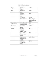
Page 28: ...Buddipole Mast W3FF 12 30 Foot Painter s Pole Costco Home Depot Most Hardware Stores Tripod Mast 6 Foot Portable Antenna Stand MFJ Tee Mount Center Tee Mount W3FF Whips SG 307 Helically Wound Whip SG...

Page 29: ...nnecting the coax to a coax pigtail 3 5 Tips Tricks 1 The most frequent source of problems in unbalanced antenna systems is the RF Ground RF grounding is frequently misunderstood and poorly implemente...

Page 30: ...and VICE VERSA Your other electronics can inject RF Noise into your receiver and obliterate your received signal completely 3 Plan your antenna installation carefully 4 Don t commit to a final install...

Page 31: ...e from http www sgcworld com ftp Books STEALTHman pdf SGC Smartuners for Stealth Antennas http www sgcworld com ftp Books stealth pdf 3 6 2 Books Carr Joseph Practical Antenna Handbook 3rd Edition McG...

Page 32: ...t Example on a sailboat use the backstay as the antenna since it is the farthest point away from the rest of the vessel 3 The antenna coupler should be installed at the feed point of the antenna 4 Alw...

Page 33: ...e could be severely damaged Never test a transmitter on the air for the first time if you are unsure about how to operate it or if you are unsure whether it is working properly You could create harmfu...

Page 34: ...remember that these models typically don t dissipate the transmitter s output as well as an oilcan dummy load The result is that RF will leak out we have heard a few stories of amateurs who were heard...

Page 35: ...as produced by CW mode operation the coupler setting will settle after a short period of time RADIO TEST PROCEDURE 1 Connect the transceiver light bulb load to the radio RF in out jack 2 Turn on the...

Page 36: ...radio to the CW mode 5 Key the PTT switch on the microphone and look at the light bulb The light should turn on if the coupler has completed its tuning cycle and if the radio is transmitting 6 For fu...

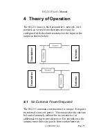
Page 37: ...ctance on the input or the output as shown below 4 1 No External Power Required The SG 211 automatic antenna tuner is unique It requires no external source of power This means that the unit can be loc...

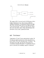
Page 38: ...the microprocessor limits standby current to a few microamperes 4 2 The Matching Network The matching network consists of a four to one step down transformer that also performs an unbalanced to balanc...

Page 39: ...hed load Locating the balun on the output side as in some other tuners means that the balun sees much more stress with a mismatched load 4 3 The Sensor Transformers T2 and T3 form a directional couple...

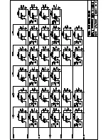
Page 40: ...hematic diagram shows the matrix used to drive the relay coils The latching relays have two coils one for turn on and one for turn off With 16 relays the circuit needs to drive 32 coils A matrix of si...

Page 41: ...of the matrix 4 5 Microprocessor A PIC flash microprocessor was selected for the very low sleep mode current drain that is key to long battery life Inputs to the microprocessor are forward and reverse...

Page 42: ...sor is used software can be changed without removing the processor or proms J1 provides connection to the programmer for this purpose Since the processor is dormant except during the actual matching p...

Page 43: ......

Page 44: ......

Page 45: ......

Page 46: ......

Page 47: ......

Page 48: ...SGC disclaims any other express or implied warranties and liability for any incidental consequential special or exemplary damages in connection with its product even if SGC or its agents are advised...

Page 49: ...5 H 32 H 64 H 64 H 32 H Output Capacitance minimum 50pf 12 5pf 25pf 12 5pf 12 5pf Output Capacitance maximum 740pf 200pf 800pf 400pf 400pf Installation Any position Any position Any position Any posit...

Page 50: ...ack or business travel A Perfect Complement to the SG 211 The SG 2020 Use it at your base or in your backpack or travel bag The SG 2020 goes where you want to go Specifications Operating Modes USB LSB...

Reviews: