


SG-211 User’s Manual
© 2004 SGC Inc.
Page 39
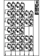
A diode pair is associated with each coil. The series
diode provides isolation necessary for proper operation of
the matrix. The shunt diode prevents voltage spikes on
turnoff.
Extensive capacitor bypassing is used to prevent RF from
interfering with the proper operation of the matrix.
On page two of the schematic diagram transistors Q1
through Q12 provide pulldown drive for the rows and
pullup drive for the columns of the matrix.
4.5
Microprocessor
A PIC flash microprocessor was selected for the very low
sleep mode current drain that is key to long battery life.
Inputs to the microprocessor are forward and reverse
power, and a sample of the input signal from which the
frequency is measured. The frequency measurement
makes it possible for the processor to store historical
values for a correct match over the frequency range.
Thus, when changing frequency, the previous values are
recalled, greatly speeding the matching process.
U2 provides a reference to one of the A/D inputs to
measure battery voltage. The processor flashes LED DS1
when a low battery condition is detected.
Summary of Contents for Smartuner SG-211
Page 1: ...Catalog Number 54 26 April 2004 The Zero Power Smartuner...
Page 4: ...SG 211 User s Manual 2004 SGC Inc Page 2 Quick Start Reference...
Page 43: ......
Page 44: ......
Page 45: ......
Page 46: ......
Page 47: ......


