25/11/2019
LEAK INDICATING UNIT
LAE 3-8
- 7 -
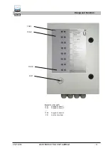
Alarm channel 1 on board 1: Red LED of the first keypad on.
Alarm channel 1 on board 2: Red LED of the second keypad on.
...
Alarm channel 1 on board 8: Red LED of the eighth keypad on.
Note:
In addition, each board has potential-free relay contacts for forward-
ing the alarm.
To forward a joint alarm, the terminals of the potential-free contacts
must be looped through.
3.3.2 Use as an indicating unit for VLX .. A-Ex tools
VLX .. A-Ex type tools can be mounted within the Ex area and are
electrically connected to the indicating unit mounted outside the Ex
area.
A tool is connected to one indicating unit board at a time. The indicat-
ing unit is connected to the potential-free contacts of the tool via the
signal circuit, and the indicating unit additionally provides the 230 V
AC power supply for the tool.
Note:
In general, it should be noted that VLX .. A-Ex tools are only connect-
ed to channel 1
.
The other channels, 2 and 3, of the indicating unit remain unused and
must be closed.
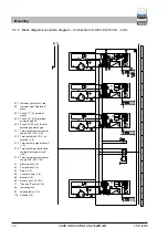
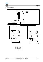
For a connection diagram, the circuit diagram, and an installation ex-
ample, see Chap. 5.4.
Technical Data


