background image


LEAK INDICATING UNIT 

LAE 3-8


                   25/11/2019


- 4 - 

The obligation of warranty shall cease to exist in the case of 
- inadequate or improper installation, 
- improper use, 
- modifications/repairs without consent of the manufacturer. 

1.6 Customer 

Service 

Our customer service is available for any inquiries. 

For information on contacts, please refer to our website 

www.sgb.de


or the label of the LAE 3-8 indicating unit. 

2. Safety 

2.1 Intended 

Use 

  Install the indicating unit 3-8 outside of the Ex area 

  Install inside a closed and dry room in buildings or alternatively in 

an outdoor protective box 

  Do not install near strong heat sources 

  Install with at least 1 m distance from the tool (VLX .. A-Ex) 

  Do not install above or below the leak detector 

  Conditions from Chap. 3.3 “Field of Application” must be adhered 

to. 

  The power supply cannot be disconnected 

Any claims arising from misuse are excluded. 

2.2  Obligation of the Operating Company 

The indicating unit 3-8 is used in the commercial sector. The operat-
ing company is therefore subject to statutory occupational safety obli-
gations. 

In addition to the safety instructions in this documentation, all appli-
cable safety, accident prevention, and environmental regulations 
must be adhered to. In particular: 

-  Compiling a risk assessment and implementing its results in a di-

rective 

-  Performing regular checks as to whether the directive is in compli-

ance with the current standards 

-  The directive includes, among others, how to react to an alarm that 

might arise 

-  Arranging for an annual functional check 


Safety 

WARNING! 

Danger from 

misuse 

WARNING! 

Danger in case 

of incomplete 

documentation 

Summary of Contents for LAE 3-8

Page 1: ...Documentation Indicating unit LAE 3 8 for VLX A Ex Read instructions prior to commencing any work As of 11 2019 Art No 605 622...

Page 2: ...ral Data 3 2 Electrical Data 3 3 Field of Application 4 Design and Function 8 4 1 Design 4 2 Displays and Controls 4 3 Alarm 5 Mounting the System 11 5 1 Basic Instructions 5 2 Mounting the Indicating...

Page 3: ...ry CAUTION Potentially hazardous situation which if not avoided could result in minor or moderate injury Information Highlights useful tips recommendations and information 1 3 Limitation of Liability...

Page 4: ...w the leak detector Conditions from Chap 3 3 Field of Application must be adhered to The power supply cannot be disconnected Any claims arising from misuse are excluded 2 2 Obligation of the Operating...

Page 5: ...assembly commis sioning and maintenance of leak detection systems 2 4 Personal Protective Equipment PPE Personal protective equipment must be worn during work Wear necessary protective equipment for...

Page 6: ...Data Power supply 100 to 240 V AC 50 60 Hz Power input 44 W Terminals60 27 61 28 62 Potential free outputs max 1 5 A for 220 V DC 250 V AC 3 3 Field of Application 3 3 1 General use The indicating uni...

Page 7: ...LX A Ex type tools can be mounted within the Ex area and are electrically connected to the indicating unit mounted outside the Ex area A tool is connected to one indicating unit board at a time The in...

Page 8: ...al strip power supply VLX A Ex 1 8 31 3 Terminal strip signal circuit VLX A Ex 1 8 31 4 Terminal strip potential free contacts for alarm forwarding 1 8 31 5 Terminal strip 24 volt for alarm forwarding...

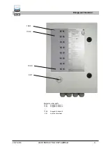
Page 9: ...5 11 2019 LEAK INDICATING UNIT LAE 3 8 9 Exterior view with 139 1 Keypad for board 1 139 2 Keypad for board 2 139 8 Keypad for board 8 69 1 Joint buzzer alarm Design and Function 139 1 139 2 139 8 69...

Page 10: ...Function Turn off audible alarm signal Briefly press the Mute button once the acoustic signal turns off and the red LED flashes No function 4 3 Alarm In the event of an alarm acknowledge the audible...

Page 11: ...Chap 7 5 3 Electrical Cables Mains connection LAE and power supply for VLX A Ex tool 5 wire 1 5 mm2 without ferrule or with ferrule without plastic collar Potential free relay contacts 6 wire 1 5 mm2...

Page 12: ...n in the case of alarm and power failure 60 62 As above but contacts closed 63 23 64 24 Channel 2 no function 63 65 As above no function 66 25 67 26 Channel 3 no function 66 68 As above no function 4...

Page 13: ...for serial data transfer 1 8 24 3 Fuse F3 100 mA fuse for switching power supply 141 Terminal strip for keypad 1 8 31 1 Terminal strip mains power supply 230 V AC 31 2 Terminal strip mains power suppl...

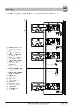
Page 14: ...24 V DC 71 Sound off switch 1 8 86 Indicating unit 87 Leak detector 1 8 139 Keypad 1 8 51 51 51 51 52 52 52 52 53 53 53 53 53 53 53 53 54 54 54 54 54 54 54 54 11 11 11 11 60 60 60 L1 L1 N N PE 60 7 7...

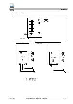
Page 15: ...Installation Example 86 Indicating unit LAE 3 8 87 Tool VLX A Ex 1 8 96 1 Buzzer 24 V DC Mounting 87 86 87 Ex 230 V AC 50 Hz Ex Ex Ex Ex pot frei 51 52 pot frei 51 52 1 8 51 52 51 52 54 53 54 53 VLX...

Page 16: ...Operation indicator lights up 6 Determination of the audible alarm for the individual connected channels For this purpose establish the alarm status at the re spective connected devices probes or ser...

Page 17: ...25 11 2019 LEAK INDICATING UNIT LAE 3 8 17 7 Dimensions and Drilling Pattern Dimensions and Drilling Pattern 295 400 260 360 7 8...

Page 18: ...n shall lose its validity Number short title Satisfied regulations 2014 30 EU EMC Directive EN 61000 6 3 2007 A1 2011 EN 61000 6 2 2005 EN 61000 3 2 2014 EN 61000 3 3 2013 2014 35 EU Low voltage Direc...

Page 19: ...25 11 2019 LEAK INDICATING UNIT LAE 3 8 19 10 T V Nord certification Certification...

Page 20: ...019 20 Text Text Legal notice SGB GmbH Hofstr 10 57076 Siegen Germany Phone 49 271 48964 0 E mail sgb sgb de Web www sgb de Photos and sketches are not binding for the scope of delivery Subject to cha...

Reviews: