background image


25/11/2019 

LEAK INDICATING UNIT 

LAE 3-8


- 11 - 

5.  Mounting the System 

5.1 Basic Instructions 

-  Prior to commencing work, the documentation must be read and 

understood. In case of ambiguities, refer to the manufacturer. 

-  The safety instructions in this documentation must be adhered to. 

-  Only qualified service companies may be used for mounting and 

commissioning

1

-  Leadthroughs for connection lines through which the explosion 

atmosphere can carry over must be sealed gas-tight. 

-  Comply with relevant regulations regarding electric installation, ex-

plosion protection (e.g. EN 60 079-14, -17), and accident preven-
tion. 

5.2  Mounting the Indicating Unit 

-  Wall mounting usually with dowels and screws in a dry room 

NOT in potentially explosive areas.


-  For housing dimensions and hole pattern, see Chap. 7. 

5.3 Electrical Cables 

Mains connection LAE and power supply for VLX .. A-Ex tool (5-wire): 

- 1.5 mm

2

 without ferrule or with ferrule without plastic collar 

Potential-free relay contacts (6-wire): 

- 1.5 mm

2

 without ferrule or with ferrule without plastic collar 

- 0.75 mm

2

 with ferrule and plastic collar or with ferrule without plastic 

collar 

External signal (2-wire): 

- 1.5 mm

2

 without ferrule or with ferrule without plastic collar 

- 0.75 mm

2

 with ferrule and plastic collar or with ferrule without plastic 

collar 

Must be resistant to stored/pumped liquids


5.4  Electrical Wiring Diagram 

(1)  Install the electrical connection securely, without plug or switch-

ing connections. 

(2)  Observe the requirements for electric installations, if necessary, 

also those of the electric companies. 

(3)  Terminal layout: (see also block diagrams in Chap. 5.4.3 and 

5.4.4) 


1

 For Germany: Specialist service companies per Water Law that have documented qualifications to install 

leak detection systems. 

Mounting 

Summary of Contents for LAE 3-8

Page 1: ...Documentation Indicating unit LAE 3 8 for VLX A Ex Read instructions prior to commencing any work As of 11 2019 Art No 605 622...

Page 2: ...ral Data 3 2 Electrical Data 3 3 Field of Application 4 Design and Function 8 4 1 Design 4 2 Displays and Controls 4 3 Alarm 5 Mounting the System 11 5 1 Basic Instructions 5 2 Mounting the Indicating...

Page 3: ...ry CAUTION Potentially hazardous situation which if not avoided could result in minor or moderate injury Information Highlights useful tips recommendations and information 1 3 Limitation of Liability...

Page 4: ...w the leak detector Conditions from Chap 3 3 Field of Application must be adhered to The power supply cannot be disconnected Any claims arising from misuse are excluded 2 2 Obligation of the Operating...

Page 5: ...assembly commis sioning and maintenance of leak detection systems 2 4 Personal Protective Equipment PPE Personal protective equipment must be worn during work Wear necessary protective equipment for...

Page 6: ...Data Power supply 100 to 240 V AC 50 60 Hz Power input 44 W Terminals60 27 61 28 62 Potential free outputs max 1 5 A for 220 V DC 250 V AC 3 3 Field of Application 3 3 1 General use The indicating uni...

Page 7: ...LX A Ex type tools can be mounted within the Ex area and are electrically connected to the indicating unit mounted outside the Ex area A tool is connected to one indicating unit board at a time The in...

Page 8: ...al strip power supply VLX A Ex 1 8 31 3 Terminal strip signal circuit VLX A Ex 1 8 31 4 Terminal strip potential free contacts for alarm forwarding 1 8 31 5 Terminal strip 24 volt for alarm forwarding...

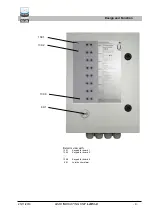
Page 9: ...5 11 2019 LEAK INDICATING UNIT LAE 3 8 9 Exterior view with 139 1 Keypad for board 1 139 2 Keypad for board 2 139 8 Keypad for board 8 69 1 Joint buzzer alarm Design and Function 139 1 139 2 139 8 69...

Page 10: ...Function Turn off audible alarm signal Briefly press the Mute button once the acoustic signal turns off and the red LED flashes No function 4 3 Alarm In the event of an alarm acknowledge the audible...

Page 11: ...Chap 7 5 3 Electrical Cables Mains connection LAE and power supply for VLX A Ex tool 5 wire 1 5 mm2 without ferrule or with ferrule without plastic collar Potential free relay contacts 6 wire 1 5 mm2...

Page 12: ...n in the case of alarm and power failure 60 62 As above but contacts closed 63 23 64 24 Channel 2 no function 63 65 As above no function 66 25 67 26 Channel 3 no function 66 68 As above no function 4...

Page 13: ...for serial data transfer 1 8 24 3 Fuse F3 100 mA fuse for switching power supply 141 Terminal strip for keypad 1 8 31 1 Terminal strip mains power supply 230 V AC 31 2 Terminal strip mains power suppl...

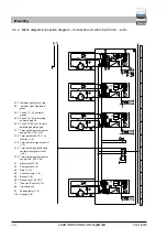
Page 14: ...24 V DC 71 Sound off switch 1 8 86 Indicating unit 87 Leak detector 1 8 139 Keypad 1 8 51 51 51 51 52 52 52 52 53 53 53 53 53 53 53 53 54 54 54 54 54 54 54 54 11 11 11 11 60 60 60 L1 L1 N N PE 60 7 7...

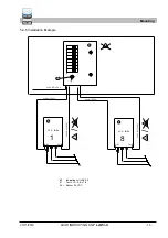
Page 15: ...Installation Example 86 Indicating unit LAE 3 8 87 Tool VLX A Ex 1 8 96 1 Buzzer 24 V DC Mounting 87 86 87 Ex 230 V AC 50 Hz Ex Ex Ex Ex pot frei 51 52 pot frei 51 52 1 8 51 52 51 52 54 53 54 53 VLX...

Page 16: ...Operation indicator lights up 6 Determination of the audible alarm for the individual connected channels For this purpose establish the alarm status at the re spective connected devices probes or ser...

Page 17: ...25 11 2019 LEAK INDICATING UNIT LAE 3 8 17 7 Dimensions and Drilling Pattern Dimensions and Drilling Pattern 295 400 260 360 7 8...

Page 18: ...n shall lose its validity Number short title Satisfied regulations 2014 30 EU EMC Directive EN 61000 6 3 2007 A1 2011 EN 61000 6 2 2005 EN 61000 3 2 2014 EN 61000 3 3 2013 2014 35 EU Low voltage Direc...

Page 19: ...25 11 2019 LEAK INDICATING UNIT LAE 3 8 19 10 T V Nord certification Certification...

Page 20: ...019 20 Text Text Legal notice SGB GmbH Hofstr 10 57076 Siegen Germany Phone 49 271 48964 0 E mail sgb sgb de Web www sgb de Photos and sketches are not binding for the scope of delivery Subject to cha...

Reviews: