


LEAK INDICATING UNIT
LAE 3-8
25/11/2019
- 12 -
1/2
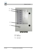
Power connection (100 to 240 V AC), wired internally
54/53 Power supply (230 V AC) for VLX .. A-Ex tool
40/41 free, no function
5/6
External signal 24 V DC (+: 5, -: 6), wired internally
51/52 Signal circuit for VLX .. A-Ex tool
21/22 Signal circuit for channel 2, must be bridged
31/32 Signal circuit for channel 3, must be bridged
Potential-free relay contacts:
60(27)/61(28) Channel 1 open in the case of alarm and power
failure
60/62
As above, but contacts closed
63(23)/64(24) Channel 2, no function
63/65
As above, no function
66(25)/67(26) Channel 3, no function
66/68
As above, no function
(4) Do not apply voltage until all electrical cables are connected and
the housing cover is closed.
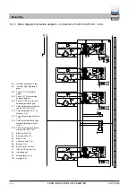
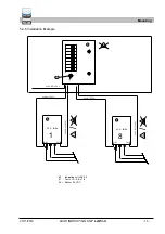
5.4.1 Connecting
the
wires
(1) Press down the orange point with a screwdriver. This opens the
tension spring of the terminal.
(2) Insert the cable into the open terminal.
(3) Hold the cable and remove the screwdriver.
(4) Check the cable for a tight fit and install more cables to the ter-
minals using the same process.
Mounting


