background image

II

Contents 

Page

Info menu ...............................................................................39

6.1 

Menu structure ........................................................................39

6.2 

Overview .................................................................................40

Adjustment menu ..................................................................43

7.1 

Menu structure ........................................................................43

7.2 

Setting the H

2

S sensor ............................................................44

7.3 

Setting the CO sensor .............................................................45

7.4 

Setting the O

2

 sensor ..............................................................46

7.5 

Setting the CO

2

 sensor ............................................................47

7.6 

Setting the CH

4

 sensor ............................................................48

7.7 

Setting the measurement quantity ..........................................50

7.8 

Setting the test gas concentration ...........................................51

7.9 

Inspection confirmation ...........................................................54

7.10 

Leaving the adjustment menu .................................................55

Memory menu ........................................................................56

8.1 

Menu structure ........................................................................56

8.2 

Clearing memory .....................................................................57

8.3 

Setting the memory interval ....................................................58

8.4 

Setting the memory mode .......................................................60

8.5 

Setting the short-term value interval .......................................61

8.6 

Leaving the memory menu ......................................................62

System menu .........................................................................63

9.1 

Menu structure ........................................................................63

9.2 

Setting the date/time ...............................................................64

9.3 

Setting the inspection interval .................................................66

9.4 

Setting the inspection block ....................................................69

9.5 

Setting the 100 vol.% range ....................................................70

9.6 

Setting the PIN code ...............................................................71

9.7 

Setting the alarm thresholds  ..................................................73

9.8 

Checking the LCD ...................................................................77

9.9 

Leaving the system menu .......................................................77

Summary of Contents for EX-TEC Combi

Page 1: ...Operating Instructions ...

Page 2: ...ours Hermann Sewerin GmbH Robert Bosch Straße 3 33334 Gütersloh Germany Tel 49 5241 934 0 Fax 49 5241 934 444 www sewerin com info sewerin com Sewerin Ltd 8 Walsworth Road Hitchin Hertfordshire SG4 9SP UK phone 44 1462 634363 www sewerin co uk info sewerin co uk Sewerin USA LLC 13551 W 43rd Drive Unit R Golden CO 80403 7272 phone 1 303 424 3611 fax 1 303 420 0033 www sewerin net jerry palmer sewer...

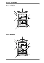
Page 3: ...Illustration EX TEC Combi EX TEC Combi Device variation 1 Device variation 2 EX TEC Combi 100 ...

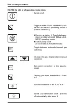
Page 4: ...ggle between GAS WARNING GAS MEASURE MENT operating modes Switch pump on off in GAS MEASUREMENT mode Toggle between automatic manual gas switching Change the gas displayed in manual operation Zero point correction for the gas dis played Display gas alarm thresholds AL1 and AL2 Acoustic clearance of the AL1 alarm Switch LCD illumination on off switches off automatically after about 4 ...

Page 5: ...Operating Instructions 15 06 2005 V2 X 103401 en EX TEC Combi ...

Page 6: ...e parts approved by us may be used for repairs Hermann Sewerin GmbH accepts no liability for damage resulting from non compliance with the foregoing The guarantee and liability provisions in the Hermann Sewerin GmbH terms of sale and supply are not extended by the foregoing We reserve the right to make changes in the context of continued techni cal development In addition to these instructions ple...

Page 7: ... Instantaneous value alarms AL1 AL2 AL3 17 3 7 Short term value alarm KZW long term value alarm LZW minimum and maximum values MIN MAX 23 3 8 Zero point adjustment 26 3 9 Illumination and contrast 26 3 10 Operating hours display and battery alarm 27 3 11 Switching off 28 4 Charging 29 4 1 Charging and charge maintenance 29 4 2 Self discharge 30 5 Testing maintenance 31 5 1 Function testing testing...

Page 8: ...ction confirmation 54 7 10 Leaving the adjustment menu 55 8 Memory menu 56 8 1 Menu structure 56 8 2 Clearing memory 57 8 3 Setting the memory interval 58 8 4 Setting the memory mode 60 8 5 Setting the short term value interval 61 8 6 Leaving the memory menu 62 9 System menu 63 9 1 Menu structure 63 9 2 Setting the date time 64 9 3 Setting the inspection interval 66 9 4 Setting the inspection block...

Page 9: ...s 80 11 2 Technical data 82 11 3 Error messages 93 11 4 Error and Alarm properties 97 11 5 Wearing Parts 98 11 6 Spare parts 98 11 7 EC Sensor Disposal 98 12 Hints on Disposal 99 13 Delivery variants and accessories 100 13 1 Delivery variants 100 13 2 Accessories 101 Appendix 108 EC type examination certificates 108 Declaration of Conformity 118 Inspection protocols 119 ...

Page 10: ...consists of the basic instrument incorpo rating a pump and a data memory for documentation purposes 4 sensor sockets for the mea surement of up to 5 different gases The following sensors are availa ble methane CH4 or propane C3H8 or nonane C9H20 carbon dioxide CO2 oxygen O2 hydrogen sulphide H2S carbon monoxide CO combined H2S CO sensor This operating manual only describes methane mea surement ...

Page 11: ...ixtures due to leaking gas pipes near the shaft due to the proximity of oil coal natural gas or LPG storage facilities due to the proximity of landfill sites marshland chemical works filling stations or refineries due to cleaning or coating work with substances containing solvents due to the prohibited introduction of combustible substances into the canal network e g petrol leaks the EC prototype tes...

Page 12: ...rom incomplete combustion e g poorly adjusted gas heating systems due to the formation of carbon monoxide near highways or car parks GAS MEASURING mode Determining gas concentrations Localisation measuring gas concentra tion in probe holes determining which probe hole has the maximum con centration Gas injection monitoring filling with natural gas and oxygen extraction measuring the methane and oxy...

Page 13: ...otection measuring function The EX TEC Combi has also been undergone a measurement function test in gas warning mode EG prototype test certificate DMT 01 ATEX G002 supplement 1 measurement range 0 100 LEL methane propane Test report PFG n 41300401 measurement range 0 25 vol oxygen measurement of oxygen defect and excess measurement range 0 5 vol of carbon dioxide measurement range 0 500 ppm of carb...

Page 14: ...iew 1 4 Carrying equipment TRIANGEL carrying system a quick and easy way of carrying the instrument consisting of a carrying strap and neck pad CROSS STRAP carrying system a comfortable way to carry the instrument for longer periods consisting of 2 carrying straps crossed at the back ...

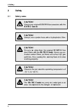
Page 15: ...not use other than the original SEWERIN fine dust filters with the EX TEC Combi Never use ac tivated carbon filters as these will collect H2S gas particles thus causing the warning feature to stop working properly CAUTION Observe the permissible operating temperature of 10 C to 40 C CAUTION The EX TEC Combi may only be recharged in an area not exposed to the danger of explosion ...

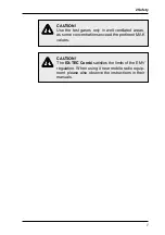
Page 16: ... in well ventilated areas as some concentrations exceed the pertinent MAK values CAUTION The EX TEC Combi satisfies the limits of the EMV regulation When using it near mobile radio equip ment please also observe the instructions in their manuals ...

Page 17: ...splay of error messages 2 LCD display of gas concentrations menu items operating conditions error messages 3 probe connection connection for probe hose test set 4 keypad instrument operation 5 attachment for carrying systems Triangel cross strap 6 outlet for the gas sample 7 buzzer acoustic warning on breaching alarm thresholds display of error messages 8 interface serial RS 232 interface for con ...

Page 18: ...illumination automati cally switches on for about 4 minutes available operating hours are displayed in the form of the battery symbol and bars e g 5 hours 5 bars the built in pump runs at con stant power the software version number e g 2 1 and instrument type Combi are displayed Note All the following instrument displays assume that the EX TEC Combi is fully equipped for the mea surement of 5 gase...

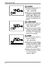
Page 19: ...range for carbon dioxide is displayed 0 00 5 00 VOL depending on your last setting a display in the VOL GAZ quantities may be possible cf section 7 7 Setting the measurement quantity O2 oxygen the measurement range for oxygen is displayed 0 0 25 0 VOL depending on your last setting a display in the VOL GAZ quantities may be possible cf section 7 7 Setting the measurement quantity display of the se...

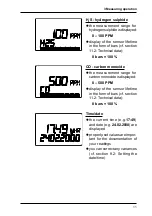
Page 20: ...ars 100 CO carbon monoxide the measurement range for carbon monoxide is displayed 0 500 PPM display of the sensor lifetime in the form of bars cf section 11 2 Technical data 8 bars 100 Time date the current time e g 17 49 and date e g 24 02 2000 are displayed properly set values are impor tant for the documentation of your readings you can correct any variances cf section 9 2 Setting the date time...

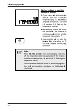
Page 21: ...nd set schedule the interval or continuous alarm may also be triggered items 1 and 7 clearing the alarm with the buzzer key or waiting for 15 secondsswitchestomeasuring operation Note If the EX TEC Combi now automatically switches off the inspection date has passed with the inspec tion block switched on cf section 9 4 Setting the inspection block The instrument does not revert to measuring opera t...

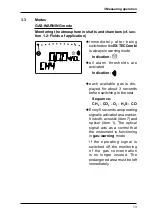
Page 22: ...ndication each available gas is dis played for about 3 seconds before switching to the next Sequence CH4 CO2 O2 H2S CO Every 5 seconds an operating signal is activated as a marker It is both acoustic item 7 and optical item 1 The optical signal acts as a control that the instrument is functioning in gas warning mode If the operating signal is switched off the monitoring of the gas concentration is...

Page 23: ...t 3 seconds inthismodeallalarmthresholds and the operating signal are switched off the pump now runs at maxi mum power NB no symbols each available gas is dis played for about 3 seconds before switching to the next Sequence CH4 CO2 O2 H2S CO in this mode depending on the task at hand you can also switch the instrument s pump on and off by briefly pressing the pump key Note IfyouwishtousetheEX TECCo...

Page 24: ...s before switching to the next Sequence CH4 CO2 O2 H2S CO Manual switching each gas is displayed until a arrow key is pressed pressing a arrow key then switches to the next gas Sequence cursor up CH4 CO2 O2 H2S CO Note In WARNING mode automatic switching always has priority If the instrument is in manual switching mode and no key has been pressed for about 10 seconds it shifts back to automatic sw...

Page 25: ...lumination item 2 switching on AL1 AL2 AL3 The instantaneous value alarm appears with all gases CH4 CO2 O2 H2S CO when the measured gas concentration exceeds or falls below a fixed threshold value KZW The short term value alarm appears with toxic gases CO2 H2S CO when the gas concentration averaged over an adjustable time period e g 15 minutes has exceeded an assessed limit value LZW The long term...

Page 26: ...ls Ex area and alarm threshold the alarm is triggered as soon as a threshold is breached Display of alarm thresholds holding down the threshold value key displays the set alarm thresholds for the per tinent gas Methane CH4 alarm thresholds factory set tings AL1 0 90 VOL 20 LEL AL2 2 20 VOL 50 LEL Carbon dioxide CO4 alarm thresholds factory set tings AL1 0 50 VOL MAK value AL2 1 00 VOL ...

Page 27: ...when the value falls below the threshold Hydrogen sulphide H2S alarm thresholds factory set tings AL1 10 PPM MAK value AL2 20 PPM Carbon monoxide CO alarm thresholds factory set tings AL1 30 PPM MAK value AL2 60 PPM Note You can alter the factory set thresholds to your own individual limits cf section 9 7 Setting the alarm thresholds ...

Page 28: ...eared the optical alarm item 1 persists if the concentration falls below this alarm threshold the opti cal and acoustic alarms items 1 and 7 switch off AL2 alarm Example CH4 exceeding this alarm threshold triggers the optical alarm item 1 the acoustic alarm item 7 the appearance of AL2 in the LCD the continuous tone is clearly distinguishable from the ope rating signal the AL2 alarm cannot be clea...

Page 29: ...rement range the AL3 alarm is reset and the AL2 alarm activated Note The AL3 alarm can be suppressed by switching to GAS MEASURING mode or switching off the instrument Note In the GAS WARNING mode 0 100 LELmethane concetrations exceeding the upper measuring range value can influence the accuracy of measurement After triggering the AL3 alarm in this measuring range the instrument must be inspected b...

Page 30: ...om pensated by a correspondingly lower adjustment of the alarm thresholds When adjusting the methane sensor with dry gas hightemperaturesandhighrelativehumidity 90 could lead to a diminished display up to 30 of measuring value This can be compensated by a correspondingly lower adjustment of the alarm thresholds Note After triggering the AL3 alarm in the CO or H2S measuring range the instrument mus...

Page 31: ...100 LEL 1 7 VOL 0 50 VOL 1 00 VOL 5 00 VOL 18 0 VOL 23 0 VOL 25 0 VOL 10 PPM 20 PPM 100 PPM 30 PPM 60 PPM 500 PPM X X NH3 50 PPM 75 PPM 100 PPM 0 15 VOL 0 35 VOL 0 7 VOL Summary All alarm thresholds factory settings and clearance facilities in brief Exception With oxygen O2 both thresholds take the form of a main alarm The AL1 alarm is triggered if the value falls below the threshold of 18 0 vol ...

Page 32: ... These can be displayed for all gases since the last time the instrument was switched on MIN value Example CO2 the minimum concentration value e g 0 25 VOL since the last time the instrument was switched on is displayed MIN appears in the LCD pressing the arrow up key brings you to the next display MAX value Example CO2 the maximum concentration value e g 0 75 VOL since the last time the instrumen...

Page 33: ...duct of the MAK value and the overshoot factor Gas MAK value Factor carbon dioxide CO2 0 50 vol 4 hydrogen sulphide H2S 10 ppm 1 carbon monoxide CO 30 ppm 2 Example a constant reading 2 00 vol 4 x 0 50 vol over 15 minutes triggers the KZW alarm main alarm which cannot be cleared KZW Example CO2 the current short term value e g 0 30 VOL since the last time the instrument was switched on is displaye...

Page 34: ...vol over 8 hours trig gers the LZW alarm main alarm which cannot be cleared LZW Example CO2 the current long term value e g 0 10 VOL since the last time the instrument was switched on is displayed LZW appears in the LCD item 2 the display of these values disappears if the on off key is briefly pressed if no key is pressed for about 10 seconds Note Both alarms KZW and LZW can be suppressed by switch...

Page 35: ...ayed max 5 from the end of the measurement range if the zero point cannot be set the sensor must be adjusted cf section 7 Adjustment menu CO2 zero point the zero point for carbon di oxide is 0 04 VOL as this is the concentration found in normal fresh air 3 9 Illumination and contrast Illumination repeatedly pressing the light key switches the LCD illumi nation on and off after about 4 minutes the ...

Page 36: ...imultaneously pressing both arrow keys during measuring operation displays the number of operating hours remaining e g 5 hours thisdisplay batterysymboland bars disappears automatically after about 10 seconds Battery alarm when the charge falls below a threshold value the battery symbol appears the alarm lamp flashes and an acoustic signal sounds the battery alarm can be cleared when the battery sy...

Page 37: ...hat the instrument must be recharged cf section 4 Charging 3 11 Switching off press the on off key for about 3 seconds the optical and acoustic control signals items 1 and 7 operate for about 3 seconds remaining operating hours are displayed in the form of the battery symbol and bars e g 5 hours 5 bars ...

Page 38: ...station HS 1 2 A AC DCadapterM4100 240V Car cable M4 12 V mounting Car cable M4 12 V mobile Car cable M4 24 V mounting Switch the EX TEC Combi off and place it in the charger A dis play on the following lines appears the instrument still has 5 ope rating hours left 5 bars and will take another 3 hours to be fully recharged if it is fully charged all the bars appear and the numerical dis play disap...

Page 39: ...s the instrument indicates no remaining operating hours and it must be recharged Note Brief periods of use and protracted disuse may in the long term lead to the co called memory effect which means that the actual battery capacity availa ble is less than what is shown in the display You can counteract this by fully discharging the EX TEC Combi regularly e g once a month leave it switched on until ...

Page 40: ...073 and EN 45544 4 provides that porta ble gas warning instruments of which the EX TEC Combi is one must be tested as stipulated in their operating instructions and immediately before use Items that the test is required to cover include the zero point and display sensitivity with a field calibra tion instrument and test gas Note In case of calibration data to multiple gas types are stored tests of ...

Page 41: ...DVGW G 465 4 Technical Communications re ference are divided into the following sections What Who When function testing user prior to start working testing display accu racy adjustment specialist or special ist company daily to half yearly servicing maintenance any repairs required SEWERIN specialist or author ised company annual on defective instru ments Function testing This is the simplest form...

Page 42: ...6 must be complied with A full function test must also be carried out Servicing maintenance and repair Instruments must be serviced and any necessary repairs car ried out at least once a year by SEWERIN Service a specialist company authorised by SEWERIN or an authorised specialist of the gas supply company These activities must be documented in writing The test plaque on the instru ment gives the ...

Page 43: ...heads B test gas connection connection for test gas cans pressure hose adapter in conjunction with pressure cyl inder and pressure reducer C manometer Display of remaining pressure inside the test gas container D release button release of test gas E fresh air supply opening for aspirating fresh air fresh air hose F needle valve with flowmeter reading the pump power in litres per hour l h G connecti...

Page 44: ...onane C9H20 zero point fresh air sensitivity replacement test gas 0 30 vol propane C3H8 in synth air reading to be a returned when replacement test gas 0 35 vol Carbon dioxide CO2 zero point fresh air sensitivity 2 0 vol CO2 in synth air Oxygen O2 zero point 100 vol methane CH4 sensitivity fresh air Hydrogen sulphide H2S zero point fresh air sensitivity 40 ppm hydrogen sulphide H2S in synth air Ca...

Page 45: ...36 5 Testing maintenance These gases are supplied in 6 test gas cans 2 2 vol CH4 2 0 vol CO2 17 5 vol O2 40 ppm CO 1 0 vol C3H8 0 3 vol C3H8 40 ppm H2S 50 ppm NH3 100 vol CH4 ...

Page 46: ...e the needle valve fig 1 item F to set the flow to maximum it must be greater than 30 l h Zero point wait for the instrument to settle at a stable zero point permis sible tolerances with fresh air are Gas Tolerance Methane CH4 0 15 0 15 vol 3 3 LEL Propane C3H8 0 06 0 06 vol 3 3 LEL Nonane C9H20 0 05 0 05 vol or 3 3 LEL Carbon dioxide CO2 0 04 0 10 vol Hydrogen sulphide H2S 3 3 ppm Carbon monoxide C...

Page 47: ...s settled at a stable value permissible tolerances with test gases Gas Tolerance Methane CH4 2 0 2 4 vol 45 55 LEL Propane C3H8 0 90 1 10 vol 54 64 LEL Nonane C9H20 0 35 0 40 vol 50 57 LEL Carbon dioxide CO2 1 8 2 2 vol Hydrogen sulphide H2S 37 43 ppm Carbon monoxide CO 37 43 ppm Ammonia NH3 47 53 ppm The oxygen sensor is tested for its sensitivity in a fresh air en vironment Tolerances Oxygen O2 ...

Page 48: ... O2 0 VOL O2 20 9 VOL CO2 0 VOL CO2 2 00 VOL CH4 0 UEG CH4 50 UEG CH4 100 VOL CH4 UEG LEL LIE VOL GAZ VOL GAZ PRÜFGAS INS OK EXIT MEM CLR MEM INT MEM STOP KZW INT EXIT DAT UHR INS INT INS STOP 100 VOL PIN CODE ALARM LCD EXIT MEMORY SYSTEM EXIT 6 Info menu 6 1 Menu structure ...

Page 49: ...he software version number e g V2 1 is displayed and the LCD illumination automati cally switches on for about 4 minutes you must now enter your PIN code cf section 9 6 Setting the PIN code 0001 factory settings only now do you have access to all menu items the pump runs at constant power it can be switched on or off with the pump key at any time the arrow up key returns you to the menu structure ...

Page 50: ...ment menu the arrow up key brings you to the next display you are now in the MEMORY menu item cf section 8 Memory menu the arrow up key brings you to the next display you are now in the menu item SYSTEM cf section 9 Sys tem menu the arrow up key brings you to the next display ...

Page 51: ...now 2 ways of con tinuing to navigate through the menu structure pressing the arrow up key returns you to the ADJUST MENT menu item cf menu structure or briefly pressing the on off key leaves the menu structure and the instrument switches to measuring operation ...

Page 52: ...M O2 0 VOL O2 20 9 VOL CO2 0 VOL CO2 2 00 VOL CH4 0 UEG CH4 50 UEG CH4 100 VOL CH4 UEG LEL LIE VOL GAZ VOL GAZ PRÜFGAS INS OK EXIT 7 Adjustment menu 7 1 Menu structure you are in the ADJUSTMENT menu item briefly pressing the on off key brings you to the adjustment menu ...

Page 53: ...CD pressing the arrow up key brings you to the next display H2S sensitivity 40 PPM now release test gas 40 PPM H2S from the SPE VOL cf section 7 8 Setting the test gas concentration wait for the display to settle at a stable value and confirm the adjustment with the on off key OK appears in the LCD once this has happened turn off the test gas feed pressing the arrow up key brings you to the CO sens...

Page 54: ... LCD pressing the arrow up key brings you to the next display CO sensitivity 40 PPM now release test gas 40 PPM CO from the SPE VOL cf sec tion 7 8 Setting the test gas concentration wait for the display to settle at a stable value and confirm the adjustment with the on off key OK appears in the LCD once this has happened turn off the test gas feed pressing the arrow up key brings you to the O2 sen...

Page 55: ...s in the LCD once this has happened turn off the test gas feed pressing the arrow up key brings you to the next display O2 sensitivity 20 9 VOL now release fresh air from the SPE VOL cf section 7 8 Setting the test gas concen tration wait for the display to settle at a stable value and confirm the adjustment with the on off key OK appears in the LCD pressing the arrow up key brings you to the CO2 s...

Page 56: ...he on off key OK appears in the LCD pressing the arrow up key brings you to the next display CO2 sensitivity 2 00 VOL now release test gas 2 00 VOL CO2 from the SPE VOL cf section 7 8 Setting the test gas concentration wait for the display to settle at a stable value and confirm the adjustment with the on off key OK appears in the LCD once this has happened turn off the test gas feed pressing the a...

Page 57: ... the LCD pressing the arrow up key brings you to the next display CH4 sensitivity 2 20 VOL nowreleasetestgas2 20 VOL 50 UEG CH4 from the SPE VOL cf section 7 8 Setting the test gas concentration wait for the display to settle at a stable value and confirm the adjustment with the on off key OK appears in the LCD once this has happened turn off the test gas feed pressing the arrow up key brings you t...

Page 58: ...ce this has happened turn off the test gas feed Note Before switching to the next step please wait until the displayed concentration has reached the value of 0 vol pressing the arrow up key brings you to the next display CH4 UEG range language repeatedly pressing the on off key switches between the fol lowing displays in the UEG range UEG display in Untere Explosionsgrenze D LEL display in Lower E...

Page 59: ...facility 7 7 Setting the measurement quantity CH4 CO2 O2 VOL range language repeatedly pressing the on off key switches between the fol lowing displays in the vol range VOL displayin VOL D GB GAZ display in GAZ F confirm the display e g VOL with the on off key OK appears in the LCD this setting is preserved even when the instrument is switched off pressing the arrow up key brings you to the test g...

Page 60: ...ing the test gas concentration if you use use test gases other than those supplied by SEWERIN the concentration must be set accordingly you are in the TEST GAS menu item briefly pressing the on off key brings you to the test gas menu Example CH4 you are now in the CH4 GAS menu item ...

Page 61: ...d e g 50 UEG 2 20 VOL you can set the desired con centration by repeatedly pressing or holding down a arrow key the selected concentration is displayed e g 45 UEG 2 00 VOL confirm the concentration with the on off key this setting is preserved even when the instrument is switched off the adjustment ranges of the individual test gas concentra tions are ...

Page 62: ... 0 50 vol 40 80 LEL step size 0 05 vol 1 LEL test gas 2 00 vol carbon dioxide CO2 adjustment range 0 90 4 10 vol tep size 0 02 vol test gas 20 9 vol oxygen O2 adjustment range 17 0 22 0 vol tep size 0 1 vol test gas 40 ppm hydrogen sulphide H2S adjustment range 10 100 ppm step size 1 ppm test gas 40 ppm carbon monoxide CO adjustment range 10 150 ppm step size 1 ppm test gas 50 ppm Ammoniak NH3 adj...

Page 63: ... mind you of scheduled inspec tion and adjustment dates this requires the inspection interval and the inspection block to be set in the system menu cf sections 9 3 Set ting the inspection interval and 9 4 Setting the inspection block confirm the inspection or ad justment you have carried out with the on off key OK appears in the LCD this date is stored as a function of the set date cf section 9 2 S...

Page 64: ... interval pressing the arrow up key brings you to the exit from the adjustment menu 7 10 Leaving the adjustment menu EXIT signpost to menu level 1 pressing the on off key leaves the adjustment menu you are now back at the top main menu level and can switch between the following menu items JUSTAGE MEMORY SYSTEM EXIT ...

Page 65: ...he EX TEC Combi continu ously stores readings from the sensors that are present these can later be read out with the appropriate evalua tion software separate user manual via the RS 232 inter face item 8 you are in the MEMORY menu item briefly pressing the on off key brings you to the memory menu ...

Page 66: ...the memory mode stack memory cf section 8 4 Setting memory mode this function enables you to clear the entire readings memory confirm the clearance with the on off key OK appears in the LCD pressing the arrow up key brings you to the memory inter val setting facility ...

Page 67: ...key brings you to the memory in terval setting facility by repeatedly pressing or holding down a arrow key you can select the following memory intervals Seconds range 1 second 10 seconds 20 seconds 30 seconds Minutes range 1 minute 2 minutes 3 minutes 5 minutes 10 minutes 20 minutes 30 minutes ...

Page 68: ...ntinuously record the following periods times in hh mm M e m o r y interval 3 gases 4 gases 5 gases 1 sec 01 02 00 41 00 29 10 sec 10 28 06 58 04 51 20 sec 20 56 13 56 09 43 30 sec 31 25 20 54 14 35 1 min 62 50 41 48 29 11 2 min 125 40 83 37 58 23 3 min 188 30 125 25 87 34 5 min 314 10 209 02 145 58 10 min 628 20 418 05 291 56 20 min 1256 40 836 10 583 52 30 min 1885 00 1254 15 875 48 Example when...

Page 69: ... Setting the memory mode MEMORY STOP you have the possibility to choose the memory mode between the ring memory or the stack memory briefly pressing the on off key brings you to the memory mode setting facility by repeatedly pressing a arrow key you can select the following memory modes OFF ring memory readings are continuously written to memory when memory is full the oldest values are over writte...

Page 70: ...value interval setting facility 8 5 Setting the short term value interval SHORT TERM VALUE INTERVAL for the meaning of the KZW alarm cf section 3 7 Short term value alarm KZW long term value alarm LZW mini mum and maximum values MIN MAX briefly pressing the on off key brings you to the short term value interval setting facility by repeatedly pressing or hold ing down a arrow key you can select the ...

Page 71: ...ved even when the instrument is switched off pressing the arrow up key brings you to the exit from the memory menu 8 6 Leaving the memory menu EXIT signpost to menu level 1 pressing the on off key leaves the memory menu you are now back at the top main menu level and can switch between the following menu items JUSTAGE MEMORY SYSTEM EXIT ...

Page 72: ...9 System menu DAT UHR INS INT INS STOP 100 VOL PIN CODE ALARM LCD EXIT SYSTEM 9 System menu 9 1 Menu structure briefly pressing the on off key brings you to the system menu you are in the SYSTEM menu item ...

Page 73: ...to the date time setting Date the last day 24 flashing and month 02 to be set are displayed by repeatedly pressing or holding down a arrow key and confirming with the on off key you can first set the day and then the month to the current date Year the last year 2000 flashing to be set is displayed ...

Page 74: ...17 flashing and minutes 49 to be set are displayed by repeatedly pressing or holding down a arrow key and confirming with the on off key you can first set the hours and then the minutes to the current time these settings are preserved even when the instrument is switched off pressing the arrow up key brings you to the inspection interval setting facility ...

Page 75: ...ou to the inspection interval setting facility Inspection interval 0 52 CW the last interval to be set is displayed in CW calendar weeks e g 0 CW function inactive 4 CW monthly 52 CW annual by repeatedly pressing or holding down a arrow key and confirming with the on off key you can set the desired interval this setting is preserved even when the instrument is switched off pressing the arrow up ke...

Page 76: ...ing inspection date is displayed for about 3 seconds on switch on lamp buzzer inactive instrument the instrument then automati cally switches to measuring operation 02 03 2004 08 03 2004 1 week before LCD the coming inspection date is displayed for about 3 seconds on switch on lamp buzzer interval lamps interval tone instrument the instrument then automati cally switches to measuring operation Dur...

Page 77: ...ter LCD the overdue inspection date is displayed on switch on lamp buzzer interval light sound instrument depending on the setting of the INS STOP function cf section 9 4 Setting the inspection block the following conditions are pos sible INS STOP OFF when the display is cleared with the buzzer key item 4 or after waiting for about 15 seconds the instrument automatically switches to measuring oper...

Page 78: ...Setting the inspection interval after that you cannot use the instrument until the inspection has been carried out and confirmed cf section 7 9 Inspection confirmation briefly pressing the on off key brings you to the inspection block setting facility Inspection block condition the last setting is displayed e g OFF block inactive ON block active by repeatedly pressing a arrow key and confirming with ...

Page 79: ...o modes cf section 3 3 Modes WARNING mode monitoring the atmosphere workplace monitoring in shafts and chambers GAS MEASURING mode determining gas concentra tions if you wish to use the instrument purely as a warning device you can switch off the 100 VOL GAS MEASURING range briefly pressing the on off key brings you to the 100 VOL range setting 100 VOL range condition the last setting is displayed ...

Page 80: ...e PIN code 9 6 Setting the PIN code PIN CODE you can set your EX TEC Combi so that only authorised persons e g instrument technicians experts have access to the info menu with all its subfunctions this involves setting a PIN code that must be entered every time the info menu is called when an incorrect PIN code is entered the instrument reverts to its switch on routine briefly pressing the on off k...

Page 81: ...ght to the desired PIN code PIN code 0000 the function is inactive every user has access to the info menu PIN code 0001 9999 the function is active only persons who know the set PIN code have access to the info menu this setting is preserved even when the instrument is switched off pressing the arrow up key brings you to the alarm thresh old setting facility Note Make a note of your PIN code and o...

Page 82: ...H2S AL1 H2S AL2 CO AL1 CO AL2 EXIT ALARM 9 7 Setting the alarm thresholds you can set your own alarm thresholds if you do not wish to use those pre set by SEWERIN you are in the ALARM menu item briefly pressing the on off key brings you to the alarm thresholds menu ...

Page 83: ...y to set alarm threshold 2 for methane CH4 the current alarm threshold is displayed e g 50 UEG 2 20 VOL by repeatedly pressing or holding down a arrow key you can set the desired alarm threshold the selected alarm threshold is displayed e g 40 UEG 1 75 VOL the setting ranges for the in dividual alarm thresholds are factory settings in bold ...

Page 84: ...95 LEL step size 1 LEL 1 LEL Nonane C9H20 LEL 0 15 vol 0 35 vol adjustment range 0 05 0 60 vol 0 10 0 65 vol step size 0 05 vol 0 05 vol Carbon dioxide CO2 0 50 vol 1 00 vol adjustment range 0 10 4 90 vol 0 20 5 00 vol step size 0 10 vol 0 10 vol Oxygen O2 18 0 vol 23 0 vol adjustment range 15 0 24 9 vol 15 1 25 0 vol step size 0 1 vol 0 1 vol Hydrogen sulphide H2S 10 ppm 20 ppm adjustment range 5...

Page 85: ...preserved even whentheinstrumentisswitched off repeatedly pressing a arrow key brings you to the exit from the alarm threshold menu EXIT signpost to menu level 2 pressing the on off key leaves the alarm thresholds menu pressing the arrow up key brings you to the LCD check facility ...

Page 86: ...ith the on off key all the possible LCD characters and symbols are activated pressing the arrow up key brings you to the exit from the menu 9 9 Leaving the system menu EXIT signpost to menu level 1 pressing the on off key leaves the memory menu you are now back at the top main menu level and can switch between the following menu items JUSTAGE MEMORY SYSTEM EXIT ...

Page 87: ...nual submitted and tested by the DMT must be followed in every respect When using the gas warning device it is essential to check whether the response times are short enough to enable its warning function to be triggered quickly enough to avoid potentially hazardous situations If necessary the alarm threshold should be set substantially below the safety threshold Please keep in mind that if the de...

Page 88: ...this name plate the manufacturer confirms that the devices meet the properties and technical re quirements described in this report Any device not bearing this name plate does not conform to the present report Upon request the operator must be supplied with a copy of this report and test report PFG No PFG Nr 41300401P ...

Page 89: ...centra tion to 100 vol or blanketing a reduction in concentration to 0 vol select GAS MEASURING mode device variation 1 with the pump key device variation 2 cf section 9 5 Setting the 100 vol range Only in this mode can measurement be reliably monitored Probe hoses The rule of thumb is the concentration display is delayed by about 1 second per metre of hose Always use SEWERIN probe hoses 1 m 2 m o...

Page 90: ...tic charge Electrostatic charges should generally be avoided Electrostatically floating objects like metallic housings with no earth connection for example are unprotected against charges transferred from dust aerosols and the like Fine dust filters There are fine dust filters in the removable probe connection item 3 and in most probes Note Heavily soiled filters should be replaced cf section 11 5 Wear...

Page 91: ...g 5 r h 90 r h short time Pressure range 800 hPa 1200 hPa Explosion protection CENELEC Testing institution Physikalisch Technische Bundesanstalt Braunschweig Test number PTB 96 ATEX 2166 1 3 supplement Identification mark II 2 G EEx ib d IIB T3 Measuring function Testing institution DMT GmbH Essen Test number DMT 01 ATEX G 002 1 supplement Measuring range 0 100 LEL methane propane PFG Number 413004...

Page 92: ...83 11 Technical aspects Pump performance Gas warning 30 l h and 150 mbar Gas measuring 50 l h and 150 mbar Sensors warm up time for all sensors 60s ...

Page 93: ...40 vol AL3 in 0 05 vol steps or 0 100 LEL AL3 in 1 LEL steps t90 time 30 seconds storage temperature 20 C 60 C for repl sensors Alarm thresholds factory settings CH4 AL1 0 90 vol AL2 2 20 vol or AL1 20 LEL AL2 50 LEL Lifetime garanteed 1 year expected 5 years Test gases zero point fresh air sensitivity 1 2 20 vol 50 LEL CH4 in synth air sensitivity 2 100 vol CH4 ...

Page 94: ...time 20 seconds storage temperature 20 C 60 C for repl sensors Alarm thresholds factory settings CO2 AL1 0 50 vol AL2 1 00 vol Temperature influence zero point up to 40 ppm CO2 C sensitivity up to 1 3 of the measuring value C Time drift 70 ppm month Cross sensivity none known Lifetime garanteed 2 years expected 5 years Test gases zero point fresh air sensitivity 2 00 vol CO2 in synth air ...

Page 95: ...0 1 vol steps t90 time 30 seconds storage temperature 0 C 20 C for repl sensors Alarm thresholds factory settings O2 AL1 18 0 vol AL2 23 0 vol Temperature influence sensitivity 0 3 Signal C Cross sensivity CO2 at5vol CO2 in23vol O2 1 O2 Lifetime garanteed 20 months expected 24 months Test gases zero point 100 vol CH4 sensitivity fresh air ...

Page 96: ... repl sensors Alarm thresholds factory settings H2S AL1 10 ppm AL2 20 ppm Temperature influence zero point no temperature influence sensitivity 0 5 Signal C Time drift 0 3 ppm month Cross sensivity at 20 C 100 ppm CO 3 ppm H2S 20 ppm CL2 1 ppm H2S 500 ppm C2H4 2 ppm H2S 2 Vol H2 100 ppm H2S 10 ppm SO2 3 ppm H2S none known Lifetime garanteed 2 years expected 3 years Test gases zero point fresh air se...

Page 97: ...seconds storage temperature 0 C 20 C for repl sensors Alarm thresholds factory settings CO AL1 30 ppm AL2 60 ppm Temperature influence zero point 5 ppm sensitivity 1 4 Signal C Time drift 0 3 ppm month Cross sensivity at 20 C 1000 ppm H2 450 ppm CO 100 ppm NO 25 ppm CO none known Lifetime garanteed 2 years expected 3 years Test gases zero point fresh air sensitivity 40 ppm CO in synthetic air ...

Page 98: ... Alarm thresholds factory settings H2S AL1 10 ppm AL2 20 ppm CO AL1 30 ppm AL2 60 ppm Temperature influence H2S zero point no influence for H2S H2S sensivity 0 5 Signal C CO zero point 5 ppm CO sensivity 1 4 Signal C Time drift H2S 0 3 ppm month CO 0 3 ppm month Cross sensivity at 20 C 300 ppm CO 3 ppm on H2S 300 ppm on CO 15 ppm H2S 15 ppm on H2S 11 ppm on CO 100 ppm H2 30 ppm on CO 5 ppm NO2 1 ppm...

Page 99: ...0 vol AL3 in 0 05 vol steps or 0 100 LEL AL3 in 1 LEL steps t90 time 30 seconds storage temperature 20 C 60 C for repl sensors Alarm thresholds factory settings C3H8 AL1 0 35 vol AL2 0 85 vol or AL1 20 LEL AL2 50 LEL Lifetime garanteed 1 year expected 5 years Test gases zero point fresh air sensitivity 1 1 00 vol 50 LEL C3H8 in synth air sensitivity 2 100 vol C3H8 ...

Page 100: ...ol steps or 0 100 LEL AL3 in 1 LEL steps t90 time 30 seconds storage temperature 20 C 60 C for repl sensors Alarm thresholds factory settings C9H20 AL1 0 15 vol AL2 0 35 vol or AL1 20 LEL AL2 50 LEL Lifetime garanteed 1 year expected 5 years Test gases zero point fresh air sensitivity 1 0 35 vol 50 LEL at 0 30 vol propane replace ment gas Note 100 vol measurement range not available ...

Page 101: ...ft 1 ppm t90 time 90 seconds storage temperature 0 C 20 C for repl sensors Alarm thresholds factory settings NH3 AL1 50 ppm AL2 75 ppm Temperature influence zero point 2 ppm sensitivity no influence Time drift 0 3 ppm month Cross sensivity at 20 C none known Lifetime garanteed 1 year expected 2 years Test gases zero point fresh air sensitivity 50 ppm NH3 in Nitrogen ...

Page 102: ...ent contact SEWERIN Service Error properties 3s alarm self resetting F18 Adjustment error Sensitivity of catalytic combustion sensor CH4 C3H8 C9H20 Remedy check test gas repeat the adjust ment contact SEWERIN Service Error properties 3s alarm self resetting F19 Adjustment error Zero point of thermal conductivity sensor CH4 C3H8 Remedy check test gas repeat the adjust ment contact SEWERIN Service E...

Page 103: ...ce Error properties 3s alarm self resetting F35 Adjustment error Sensitivity in the H2S or CO range EC Remedy check test gas repeat the adjust ment contact SEWERIN Service Error properties 3s alarm self resetting F36 Adjustment error Zero point in the CO2 range IR Remedy check test gas repeat the adjust ment contact SEWERIN Service Error properties 3s alarm self resetting F37 Adjustment error Sens...

Page 104: ...nsor error H2S Measurement range falling below 3 ppm Remedy adjust or replace the H2S sensor Error properties self resetting non clearable F50 Microcontroller ROM Test Self test faulty Remedy switch the device off on again SEWERIN Service Error properties self retaining non clearable F51 Microcontroller RAM Test Self test faulty Remedy switch the device off on again SEWERIN Service Error propertie...

Page 105: ...e Error properties self retaining non clearable F62 Sensor error thermal conductivity Sensor error occured in the GAS WARNING mode GAS MEASURING mode Remedy switch the device off on again SEWERIN Service Error properties clearable F75 F78 Sensor component error Remedy switch the device off on again SEWERIN Service Error properties self retaining non clearable F100 Pump performance too low Switch t...

Page 106: ...e when the level falls once again below the alarm threshold AL3 End of measuring range Sensor reached end of measuring range Alarm properties self resetting when the level falls below the end of measuring range 11 4 Error and Alarm properties All Fxxx errors do have highest priority i e they can only be run as sole errors Errors F40 F44 and F62 are exceptions These messages can occur together with...

Page 107: ...d 6 m probe hoses Test gas can various concentrations for monitoring and adjustment Note Test gas can are under pressure do not store above 50 C Observe the storage time 11 6 Spare parts Note When ordering spare parts please check the relevant standard offers for reference 11 7 EC Sensor Disposal Note EC Sensors must be disposed of by at a special disposal site ...

Page 108: ...erned by the European Waste Catalogue EWC Type of Waste Corresponding EWC Code Instrument 16 02 13 Test gas can 16 05 05 Battery accu 16 06 05 Old Instruments Old instruments can be returned to Hermann Sewerin GmbH We will arrange the qualified disposal free of charge through certified specialists ...

Page 109: ...13 Delivery variants and accessories 13 1 Delivery variants EX TEC Combi Part No MG02 10001 Multiple Gas Warning Device with built in pump data storage and serial port with space to plug in 4 sensors for the monitoring of max 5 different gases ...

Page 110: ... adapter M4 Part No LD10 10001 to connect the docking station HS 1 2 A to a 100 240 volt mains Car cable 12 V mounting Part No ZL07 10000 to connect the docking station HS 1 2 A to 12 volt vehicle electrics with built in fuse and blade receptacles Car cable M4 12 V mobile Part No ZL07 10100 to connect the docking station HS 1 2 A to 12 volt vehicle electrics with built in fuse and connector for ci...

Page 111: ...angel Part No 3209 0005 upholstered back belt and 4 point tightening method Carrying system Cross Belt Part No 3209 0004 2 belts to be crossed over on the back and 4 point tightening method Carrying bag VT SR Part No 3204 0033 leather with inspection win dow and recesses for instru ment connections 4 belt eyes for tightening carrying systems Triangel and Cross Belt flap with velcro fastening to be ...

Page 112: ...103 13 Delivery variants and accessories Case VT SR Part No ZD08 10000 with built in partitions charging possibility from the outside Case VT SR universal Part No ZD11 10000 with built in partitions ...

Page 113: ...ired Flexible hand probe Part No ZS32 10000 360 mm long flexible tip with fine dust filter probe hose 1 m will be re quired Telescopic hand probe Part No ZS43 10000 flexible tip with fine dust filter with probe hose minimum length 450 mm maximum length 930 mm Floating probe Part No ZS21 10100 to monitor the working place probe hoses 2 m or 6 m will be required ...

Page 114: ... probe hose 1 m will be re quired Trench probe Part No ZS03 10400 345 mm probe tip for localization within trenches with probe filter inset probe hose 1 m will be re quired Probe hose 1 m long Part No ZS25 10000 with hydrophobic filter and quick connect Probe hose 2 m long Part No ZS17 10100 with hydrophobic filter and quick connect ...

Page 115: ...ons in 1 litre cans under pres sure of approx 12 bar Testing Technique Test set SPE VOL Part No PP01 90101 for mobile vehicle mounting connection for all SEWERIN test gas cans flow rate control release key and connecting hose Test set SPE2 Part No PP01 70001 for non mobile use in the workshop with connections for several SEWERIN pressure cylinders pressure and flow meter re lease key and connection ...

Page 116: ... dis play sensitivity various test gas concentra tions in 0 4 2 0 10 0 litre steel cylinders under pressure of 100 150 bar Carbon dioxide filter to filter out CO2 shares within test gas samples with Rectus plug connections also for adjusting the CO2 sensor Test manometer for test gas cans manometer 0 16 bar with valve adapter for SEWERIN test gas cans ...

Page 117: ...108 Appendix ...

Page 118: ...109 Appendix ...

Page 119: ...110 Appendix ...

Page 120: ...111 Appendix ...

Page 121: ...112 Appendix ...

Page 122: ...113 Appendix ...

Page 123: ...114 Appendix ...

Page 124: ...115 Appendix ...

Page 125: ...116 Appendix ...

Page 126: ...117 Appendix ...

Page 127: ...0 081 1 EMV Fachgrundnorm Störaussendung Generic Emission Standard DIN EN 50 082 1 EMV Fachgrundnorm Störfestigkeit Generic Immunity Standard DIN EN 50 014 18 20 Ex Allgemeine Bestimm Druckf Kapselung Eigensicherheit General Requirements Flameproof Encl Intrinsic Safety i DIN EN 50 054 057 271 El Geräte für das Aufspüren brennbarer Gase El devices to detect and measure combustible gases Fundstelle...

Page 128: ...5 vol or display 3 3 LEL 3 2 test gas 2 2 vol CH4 50 LEL display 2 0 2 4 vol or display 45 55 LEL 3 3 test gas 100 vol CH4 display 98 102 vol 4 0 CO2 range 4 1 zero point fresh air display 0 04 0 10 vol 4 2 test gas 2 0 vol CO2 display 1 8 2 2 vol 5 0 O2 range 5 1 zero point test gas 100 vol CH4 display 0 5 0 5 vol 5 2 test gas fresh air display 20 4 21 4 vol 6 0 H2S range 6 1 zero point fresh air...

Page 129: ...120 Appendix 8 0 Alarm function 8 1 optical alarm e g Y N 8 2 audible alarm e g Y N 9 0 Observations housing broken adjustment repair factory inspection or the like 10 0 Test day month year signature ...

Page 130: ...06 vol display 3 3 LEL 3 2 test gas 1 0 vol C3H8 59 LEL display 0 9 1 1 vol or display 54 64 LEL 3 3 test gas 100 vol C3H8 display 98 102 vol 4 0 CO2 range 4 1 zero point fresh air display 0 04 0 10 vol 4 2 test gas 2 0 vol CO2 display 1 8 2 2 vol 5 0 O2 range 5 1 zero point test gas 100 vol CH4 display 0 5 0 5 vol 5 2 test gas fresh air display 20 4 21 4 vol 6 0 H2S range 6 1 zero point fresh air...

Page 131: ...122 Appendix 8 0 Alarm function 8 1 optical alarm e g Y N 8 2 audible alarm e g Y N 9 0 Observations housing broken adjustment repair factory inspection or the like 10 0 Test day month year signature ...

Page 132: ...ir display 0 05 0 05 vol or display 3 3 LEL 3 2 replacement test gas 0 3 vol propane display 0 3 0 4 vol or display 43 57 LEL 4 0 CO2 range 4 1 zero point fresh air display 0 04 0 10 vol 4 2 test gas 2 0 vol CO2 display 1 8 2 2 vol 5 0 O2 range 5 1 zero point test gas 100 vol CH4 display 0 5 0 5 vol 5 2 test gas fresh air display 20 4 21 4 vol 6 0 H2S range 6 1 zero point fresh air display 3 3 ppm...

Page 133: ...124 Appendix 8 0 Alarm function 8 1 optical alarm e g Y N 8 2 audible alarm e g Y N 9 0 Observations housing broken adjustment repair factory inspection or the like 10 0 Test day month year signature ...

Page 134: ...Hermann Sewerin GmbH Robert Bosch Straße 3 33334 Gütersloh Germany Telefon 49 5241 934 0 Telefax 49 5241 934 444 www sewerin com info sewerin com 15 06 2005 103401 en ...

Reviews: