


8
Movitrac
®
31.. – FRS 31
3
Commissioning
3
Commissioning
3.1
Before you start
Master and slave drives must first be commissioned as stand-alone drives in V/f mode, then for
speed control and then, as third step, for synchronous operation:
1.
Commissioning
for
V/f mode
of each master and slave drive (see MOVITRAC
®
31.. Operating
Instructions).
2.
Commissioning for speed control
of each slave drive; and of master, if this is not only to be
used in V/f mode (see MOVITRAC
®
31.. Operating Instructions).
3.
The slave drives can then be set up for
synchronous operation
(see section 4 ‘Commission-
ing’ and section 5 ‘Parameters’).
Notes on project planning:
• If identical speeds of master and slave(s) are required when free-running, the internal fixed
setpoints (n11/n12/n13/fmin) must be used instead of the external analogue setpoints.
• If similar drives are used in synchronous operation (e.g. multicolumn hoist), the most heavily
loaded drive should be selected as the master.
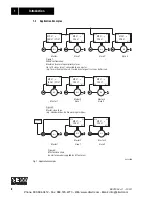
• In a group configuration (1 master and x slaves on the same level) up to 5 units can be
connected to 1 master binary output.
3.2
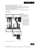
Wiring information
• The maximum permitted cable lengths are as follows:
– between master and slave drive(s) (max. 10 slaves to 1 master): 8 m or 26.4 ft
– between master or slave and associated incremental encoder: 150 m or 495 ft
• A cable break between master or slave drive and the associated incremental encoder is monito-
red by the unit itself as soon as the speed control function is activated (P 770 = speed control).
When a fault occurs, the message “Error 11 speed measurement” is generated.
• A cable break between master and slave is monitored by the “cable break master - slave”
function (on the slave: P 557 = Yes). This requires:
– Connection from master: binary output “zero speed” (P 61x) to slave: binary input: “FRS
CTRL” (P 60x). In the case of master-slave chain configurations, the slave must be connected
to the master from which it receives its setpoint. If the setpoint cannot be sent from the
master to slave or the master-slave connection is down, the message “Error 36 master slave
connection” is generated.
– Connection from slave: binary output “Fault” (default terminal 62) to master: binary input
“Ext. error” (P 60x).
– Connection of electronic reference potential (terminal 30) from the master to the slave(s).
Master fitted with FEN 31 Speed Detection and Speed Control activated (P 770 = Yes).
– Use of incremental encoders with 512/1024 or 2048 pulses/revolution (P 773).
Open-circuit monitoring is not suitable for encoders with 256 or less pulses.
• Enable command for synchronous operation on slave unit:terminal 43 = “1” (enable) and
terminal 41 = “1” (CW) or terminal 42 = “1” (CCW).
Note: The direction of rotation information provided by the setpoint pulses from master to slave
determines the direction of rotation of the slave during synchronous operation.
• Synchronous operation with constant starts and stops:
Lowest possible angular offset of the slave in relation to the master through:
– Slave permanently enabled, i.e. terminal 43 = “1” and terminal 41 or 42 = “1”.
– Program a binary output on the master as “rotating field on” (P 61x).
– Connection from master: binary output “rotating field on” to slave: binary input “FRS slave
start” (P 60x).
– Activate the “setpoint stop function” on the slave (P 180 = On).
– Set the same premagnetisation time (P 326) on the master and slave (e.g.
≤
100 ms).
Phone: 800.894.0412 - Fax: 888.723.4773 - Web: www.clrwtr.com - Email: [email protected]


