


MOVITRAC
®
31.. – FRS 31
7
Wiring Diagram
2
2
Wiring Diagram
00587AEN
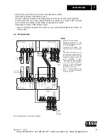
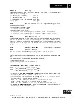
Fig. 2: FEN 31 and FES 31 wiring diagram
FEN 31 Speed Detection Operation
X5
81 Output: channel A
Setpoint pulses for slave
(5 V - TTL, RS-422)
not required for slave(s)
82 Output: channel A
83 Output: channel B
84 Output: channel B
85 Output: channel C
86 Output: channel C
87 Reference potential for terminals
X6
88 Input: channel A
Connecting encoder
The A
→
B channel sequence means:
motor runs clockwise
(as seen from motor output shaft end),
i. e. channel A leads channel B when the fan
rotates counter-clockwise
89 Input: channel A
90 Input: channel B
91 Input: channel B
92 Input: channel C
93 Input: channel C
94 Encoder power supply (+ 5...8 V)
For measuring voltage on encoder (if sensor leads
are not connected, then leave TLs 95 and 96 open)
95 Sensor line (+ 5 V)
96 Reference potential of terminal 95
97 Reference potential of terminal 94
FES 31 Synchronous Operation Option
X18
44 + 24 V
48
Binary inputs (optically isolated)
49 If there is a “1” on terminal 50, parameter set 2 is used and synchronous operation is disabled
50 R
i
= 3.0 k
Ω
(DIN 19240) + 13 to + 33 V
=
“1” = contact closed
51 -3 to + 7 V
=
“0“ contact open (can be allocated as required; signal types
→
P 60_)
60
Reference potential
for terminals 48/49/50/51
30
Reference potential
24 V
63
Binary outputs
64 R
i
= 100 k
Ω
Max. current loading I
max
= 50 mA, driver for max. 5 binary inputs (assignable; signal types
→
P 61_)
X16:
98 Input from master: channel A
99 Input from master: channel A
100 Input from master: channel B
101 Input from master: channel B
X17:
102 “1” = Free-running (+ 24 V) “0” = synchronous operation
103 “1” = Offset 1 (+ 24 V) “0” = without angular offset
104 “1” = Offset 2 (+ 24 V) “0” = without angular offset
105 “1” = Offset 3 (+ 24 V) “0” = without angular offset
0V
En
co
de
r
su
pp
ly
0V
Sens
or
+5
V
Sens
or
+5
V
(300mA)
En
co
de
r
su
pp
ly
Channel C/
only required
for output via TL. 85/86
C
Screen
FEN 31 Speed Detection
FRS ZERO POINT
0/1 = free-running
0/1 = reset*
reference 48-51
1/0 = no faults / Ixt warning*
0/1 = Iref*
0/1 = offset 1
0/1 = offset 2
0/1 = offset 3
81
98
82
99
83
10
0
84
10
1
85
86
87
88
44
89
48
10
2
90
49
10
3
91
50
10
4
92
51
10
5
93
60
94
30
95
30
96
63
97
64
X5:
X18:
X6:
X16:
X17:
0V10
A
A
A
A
B
B
B
B
C
C
A
A
B
B
C
C
6
Encoder 5V TTL
X0:
X21:
X20:
FES 31 Synchronous Operation
* factory setting
+2
4
V
FRS
SLA
VE
ST
ART
0V24
0V24
Phone: 800.894.0412 - Fax: 888.723.4773 - Web: www.clrwtr.com - Email: [email protected]


