


MOVITRAC
®
31.. – FRS 31
5
Introduction
1
The principle behind synchronous operation is the continuous comparison of the angular position
between the slave motor and the master. For this purpose, the master and slave motors should be
fitted with encoders (pulse encoders) that output the same number of pulses. A MOVITRAC
®
31..
with the FRS 31.. option is used as the slave drive. The FRS 31.. option comprises the FEN 31..
Speed Detection Option and the FES 31.. Synchronous Operation Option. Synchronous operation
of master and slave requires that the slave be fitted with a braking resistor. The master can, in
some cases, require a braking resistor for regenerative operation.
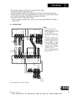
The FES 31.. Synchronous Operation Option is installed in the MOVITRAC
®
31... at connector X20.
This prevents connector X20 from being used for any other option. Parameter set 1 is the only set
of parameters that can be used for both synchronous operation and speed control.
The master drive can be operated either with a MOVITRAC
®
31.. in V/f mode or under speed control
or, without a frequency inverter, directly from the mains. If supplied directly from the mains, the
encoder of the master drive must have its own external voltage supply. If the signal “zero speed” is
used in conjunction with open-circuit monitoring in the case of MOVITRAC
®
31.. operation, the
master must also be fitted with the FEN 31.. Speed Detection option and have speed control activa-
ted.
Note:
We suggest that the maximum frequency (P202) of the slave drive be set higher than that of the
master drive (at least 10 Hz).
An internal counter in the slave counts the differences in pulses compared with the master, i.e. the
difference in the angular position of the master and slave.
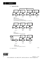
This counter is evaluated differently depending on the mode of operation (P 764):
•
In synchronous operation
(= all modes 1-8) the internal counter is used to correct the angular
offset to
∆α
= 0.
• The internal counter is disabled when the slave is
free-running (mode 1)
.
•
In limited free-running mode
, the internal counter records the required pulse difference and
processes it according to the mode of operation selected:
in modes 2/4:
free-running for a limited period, then return to previous angular position
relative to the master,
in modes 3/5/8:
free-running for a limited period, then use new angular position relative to the
master.
• In
synchronous operation with angular offset
, the internal counter corrects a variable angular
offset
∆α
= the offset between master and slave:
in mode 6:
angular offset for a limited period, then return to previous angular position
relative to the master,
in mode 7:
continuous angular offset (phase trimming)
Phone: 800.894.0412 - Fax: 888.723.4773 - Web: www.clrwtr.com - Email: [email protected]


