SEW MOVITRAC 31 Manual Download Page 15

MOVITRAC 

®

  31.. – FRS 31

15

Parameters

4

P 611 to 617

Binary outputs 

The programmable binary outputs on terminals 62/63/64 can be allocated the following signals in
addition to the usual signal types:
• “FRS alert signal” (see P 550)

active low

• “FRS lag error” (see P 551)

active low

• “Slave in position” (see P 554 and P 556) active high
• “Zero speed”

active high

P 760

Synchronous Operation

Yes / No

     (only with FRS 31A option package)

Setting (when unit disabled):
• on slave with FRS 31 option package:

set synchronous operation = “YES”

• on master with FEN 31 option pcb:

synchronous operation = “NO” and speed control (P 770) = “NO”:

normal V/f mode

synchronous operation = “NO” and speed control (P 770) = “YES”:

speed control mode 

P 761

MOVITRAC

®

  is master/slave

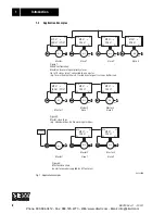
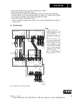
TThis parameter determines the role of the appropriate unit/drive. Terminals 98 to 101 of the unit
defined as the “SLAVE” must receive pulses from the pulse output on terminals 81 to 84 of the
master. The appropriate wiring must be taken into account (see terminal connection diagram and
application examples). Setting a unit as the “SLAVE” will automatically activate speed control
(P 770).

P 762

Gear ratio factor master       

Value range = 1...3.999.999.999

P 763

Gear ratio factor slave

These two parameters determine the angular velocity ratio of the slave to the master.

The following factors for master and slave drives must be taken into account during the calcula-
tion:
• exact gear ratios. To just two decimal places in the SEW catalog.
• input transmission ratios
• pulley diameter (including twice the belt thickness)

The 

ratio between P 763 / P 762

  is therefore calculated as:  

• In cases of the 

same type of synchronized drives

 with identical gear ratios (including input

transmission), the value of both parameters will be “1”.

• If the ratio between P 762 and P 763 

with the same type of drive

 is # 1, proportional operation

with an appropriate ratio can be selected. Examples:
P 763 = 101 / P 762 = 100 

 slave drive runs 1.01 times faster than the master.

P 763 = 5 / P 762 = 10 

 slave drive runs half as fast as the master.

P 763 = 4444 / P 762 = 2000 

 slave drive runs at 2.222 times the speed of the master.

• Where the 

drives are of different types

 (example: main drive and feed drive for flying saws), the

desired angular velocity ratio can be specified.

P 763

=

(i

gear

 • i

input transmission

) slave • pulley diam

master

P 762

(i

gear

 • i

input transmission

) slave • pulley diam

slave

Phone: 800.894.0412 - Fax: 888.723.4773 - Web: www.clrwtr.com - Email: [email protected]

Summary of Contents for MOVITRAC 31

Page 1: ...08 198 96 T MOVITRAC 31 Frequency Inverters Manual FRS 31 Synchronous Operation Control Edition 10 98 0922 4319 1198 ...

Page 2: ...t of fault free operation and fulfilment of any rights to claim under guarantee is that these instructions and notes are followed This manual contain important information for servicing and should be kept near the unit This manual does not replace the detailed MOVITRAC 31 Operating Instructions Equipment may only be installed by qualified electrical personnel in compliance with the applicable acci...

Page 3: ... Parameters 10 4 1 Relationship between parameter values and output speed 10 4 2 Signal functions 10 4 3 Explanation of the parameters 12 5 Fault Messages 18 6 Technical Data 19 Modifications to the previous version edition 02 97 Synchronous operation has been expanded with Mode 8 The manual now contains a description of Mode 8 Phone 800 894 0412 Fax 888 723 4773 Web www clrwtr com Email info clrw...

Page 4: ... restricted free running operation When the angular difference between slave and master is the same as the value of P 765 free running terminates and the angular difference is reduced to zero i e synchronous operation of slave with previous position in relation to master As mode 2 though returns automatically to synchronous operation 5 Free running operation limited by value of P 7651 1 signal pul...

Page 5: ... circuit monitoring in the case of MOVITRAC 31 operation the master must also be fitted with the FEN 31 Speed Detection option and have speed control activa ted Note We suggest that the maximum frequency P202 of the slave drive be set higher than that of the master drive at least 10 Hz An internal counter in the slave counts the differences in pulses compared with the master i e the difference in ...

Page 6: ...MC 31 FRS 31 M1 n1 M2 n2 M3 n3 M1 n1 M2 n2 M3 n3 Master 1 Master 2 Slave 1 Master 3 Slave 2 X6 X16 X17 X5 MC 31 FRS 31 X6 X16 X17 X5 MC 31 FRS 31 Figure 3 Master slave chain power for encoder supplied by M 1 external Power supply 5VDC Figure 2 Master slave chain e g calendar drives bottle washing machines Figure 1 Group configuration Master and several equal priority slaves Up to 10 slaves max con...

Page 7: ... Ri 3 0 kΩ DIN 19240 13 to 33 V 1 contact closed 51 3 to 7 V 0 contact open can be allocated as required signal types P 60_ 60 Reference potential for terminals 48 49 50 51 30 Reference potential 24 V 63 Binary outputs 64 Ri 100 kΩ Max current loading Imax 50 mA driver for max 5 binary inputs assignable signal types P 61_ X16 98 Input from master channel A 99 Input from master channel A 100 Input ...

Page 8: ...aster and slave is monitored by the cable break master slave function on the slave P 557 Yes This requires Connection from master binary output zero speed P 61x to slave binary input FRS CTRL P 60x In the case of master slave chain configurations the slave must be connected to the master from which it receives its setpoint If the setpoint cannot be sent from the master to slave or the master slave...

Page 9: ...5 X6 X5 X6 S12 S22 S21 S23 S24 S25 S26 S27 A A B B A A C C B B A A C C B B A A C C B B 0V10 10V 0V10 0V24 0V24 24V 86 87 C C 0V10 85 FEN 31 FPI 31 10V FES 31 FEN 31 Reference 41 47 Earth encoder Earth sensor 5V sensor 5V encoder FREE RUNNING factory setting 1 0 IXT WARNiNG Reference 48 51 FRS ZERO FAULT BRAKE RELEASED n in free running mode setp MC 31 slave Encoder slave Encoder master Master setp...

Page 10: ...gear output shaft igear unit If in addition to the speed of the motor and the gear ratio the input transmission also has an impact on the effective output speed of the machine the number of motor revolutions should be calculated as follows Motor revolutions Revolutions of output shaft Igear finput transmission 4 2 Signal functions The following operating states occur Visual signal on LED V11 green...

Page 11: ...ica tions with FRS 31 only 550 FRS alert signal 50 99 999 999 551 FRS lag error 100 4000 99 999 999 552 Hold time 1 99 s 553 Error response 0 1 signal coast to rest stop rapid stop 554 Positional tolerance of slave 10 25 32768 555 LED counter V11 10 100 32768 556 Time constant position signal 5 10 2000 ms 557 Cable break master slave J N 600 606 Binary inputs terminals 42 43 47 48 49 50 51 Also av...

Page 12: ...e of the inverter can also be programmed P 553 The signals are active when low In modes 3 5 and 8 the point of synchronization will already be the new cutting position when the free running terminal is actuated The FRS alert signal and FRS lag error messages therefore already apply to this point so can be used for time optimized positioning of the saws in a Flying Saws application In modes 6 and 7...

Page 13: ... 556 P 557 Cable break master slave Yes No Monitoring of the setpoint line between the master and the slave uses the connection between the binary output zero speed on the master and the binary input FRS CTRL on the slave as a refer ence signal If zero speed 0 and the FES 31 pcb is not receiving any setpoint input the unit assumes a cable break on the setpoint line or the line between zero speed a...

Page 14: ... teach in terminal to 1 approach reference point 2 switch FRS teach in terminal to 0 switch drive to synchronous operation terminal 102 0 value entered for P 765 is no longer valid and is indicated by an asterisk 00590AEN Fig 4 FRS teach function The drive synchronizes itself afterwards to reference point 2 Notes on approaching the reference points a approaching the reference points by saw carriag...

Page 15: ...ear ratio factor master Value range 1 3 999 999 999 P 763 Gear ratio factor slave These two parameters determine the angular velocity ratio of the slave to the master The following factors for master and slave drives must be taken into account during the calcula tion exact gear ratios To just two decimal places in the SEW catalog input transmission ratios pulley diameter including twice the belt t...

Page 16: ... of P765 reached Slave then reduces the angular difference to zero i e synchronous operation in previous position relative to master 1 Inactive active ON 5 Free running limited by value of P 765 with new reference point 1 signal pulse duration 100 ms initiates start of limited free running Free running ends when value of P765 reached Slave then switches to synchronous operation with this new value...

Page 17: ...n it reaches the new reference point This assumes a suitable setpoint value when the slave is in free running mode In mode 8 the Slave counter parameter as with mode 3 specifies a new reference point for the slave relative to the master Before the new reference point is set the internal counter for the angular offset is set to zero The difference values are entered with a sign Display value slave ...

Page 18: ... connection to slave terminals 98 101 lost reference signal from zero speed binary output on master FRS CTRL binary input on slave lost no input on slave has been assigned to FRS CTRL no output on master has been assigned to zero speed no master inverter present encoder with 512 pulses revolution speed control mode on master FRS PARAMETER DATA FAULT disabled 37 FRS RAM FAULT Immediate switch off I...

Page 19: ... der Winkeldifferenz LED V12 red ON angular difference value of P555 OFF angular difference value of P555 ON slave is free running OFF slave is synchronous Binary inputs Isolated via opto couplers Rj 3 kΩ sample time 5ms EN 61131 2 IE 10 mA PCL compatible Voltage level 13 30 V 1 contact closed 3 5 V 0 contact open Control functions TL 102 TL 103 104 105 TL 48 49 50 51 for modes 1 8 1 free running ...

Reviews: