background image

88

Operating Instructions – MOVIDRIVE® MDR60A/61B

8

Error messages and list of errors

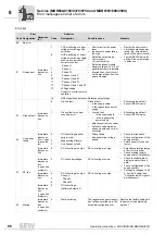
Service (MDR60A0150/0370/0750 and MDR61B1600/2500)

44

Unit utilization

Immediate 
disconnec-
tion 

0

Unit utilization error

Unit utilization (IxT value) 
> 125%

Decrease power output

Extend ramps of the motor 
inverter

If suggested actions not 
possible, use larger regen-
erative power supply unit.

Reduce load

45

Initialization

Immediate 
disconnec-
tion (+ open 
line contac-
tor)

1

Offsets of the current mea-
surement outside the per-
mitted range

No parameters set for 
EEPROM in power section, 
or parameters set incor-
rectly.

Option card not in contact 
with backplane bus.

Current measurement is 
defective

Error in the processor 
periphery

Restore factory settings 
Consult SEW Service if 
the error still cannot be 
reset.

Insert the option card cor-
rectly.

47

System bus 1 
timeout

No 
response, 
(display 
only)(P)

0

Timeout system bus 
CAN1

Error during communication via 
system bus 1.

Check system bus connection.

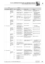
80

RAM test

Immediate 
disconnec-
tion 

0

"RAM test" error

Internal unit fault, RAM defec-
tive.

Consult SEW Service.

94

Unit configu-
ration data

Immediate 
disconnec-
tion 

1

CRC checksum error

Inverter electronics disrupted, 
possibly due to effect of EMC or 
a defect.

Send unit in for repair.

11

Power section data CRC 
checksum error

97

Copy error

Immediate 
disconnec-
tion 

1

Download of parameter 
set to unit cancelled.

Memory card cannot be 
written or read.

Error during data transmis-
sion

Repeat copying process

Restore default setting 
(P802) and repeat copying 
process

98

CRC error 

Immediate 
disconnec-
tion (+ open 
line contac-
tor)

0

"CRC via internal flash" 
error

Internal unit error, flash memory 
defective.

Send unit in for repair.

107

Line compo-
nents 

Immediate 
disconnec-
tion (+ open 
line contac-
tor)

1

Line contactor feedback 
contact error

Defective main contactor

Supply cable missing 

Output stage defective

Control cables defective

Check main contactor

Check control cables and 
line connection

Check line filter connec-
tion

4

Internal line cables are 
swapped

5

Missing line cable or faulty 
branch of the output stage

6

Unable to perform self-test 
due to controller inhibit.

124

Ambient con-
dition

Immediate 
disconnec-
tion 

1

Permitted ambient tem-
perature exceeded

Ambient temperature > 60 °C

Improve ventilation and cool-
ing conditions, improve air 
supply in the control cabinet, 
check filter mats.

Error

Suberror

Code Designation

Response 
(P)

Code

Designation

Possible cause

Measure

Summary of Contents for MDR60A

Page 1: ...Drive Technology Drive Automation System Integration Services Operating Instructions MOVIDRIVE MDR60A 61B Regenerative Power Supply Unit Edition 06 2011 19300816 EN...

Page 2: ...SEW EURODRIVE Driving the world...

Page 3: ...of delivery 14 3 3 Size 2 15 3 4 Size 3 16 3 5 Size 4 17 3 6 Size 6 18 3 7 Size 7 19 4 Installation MDR60A0150 0370 0750 and MDR61B1600 2500 21 4 1 Installation notes 21 4 2 Information regarding UL...

Page 4: ...ty 102 11 5 Fuses and cable cross sections 103 12 Installation MDR60A1320 503 00 104 12 1 Mechanical installation 104 12 2 Notes on electrical installation 105 12 3 Electrical connection 107 12 4 Inst...

Page 5: ...Operating Instructions MOVIDRIVE MDR60A 61B 5 Contents 17 Declarations of Conformity 139 17 1 MOVIDRIVE MDR60A 61B 139 Index 140...

Page 6: ...to property and other notes 1 2 2 Structure of the section related safety notes Section safety notes do not apply to a specific action but to several actions pertaining to one subject The used symbols...

Page 7: ...of the MOVIDRIVE MDX60B 61B regenerative power supply unit and to achieve the specified product characteristics and performance requirements SEW EU RODRIVE assumes no liability for injury to persons o...

Page 8: ...regenerative power supply units can have live bare and movable or rotating parts as well as hot surfaces depending on their degree of protection Removing covers without authorization improper use as...

Page 9: ...tart of designated use is only permitted under observance of the EMC 2004 108 EC directive Regenerative power supply units meet the requirements stipulated in the low voltage di rective 2006 95 EC The...

Page 10: ...nce with pertinent regulations e g cable cross sections fusing protective conductor connection For any additional infor mation refer to the applicable documentation You will find notes on EMC complian...

Page 11: ...ation The fact that the status LED and other display elements such as the display LED on size 7 units are no longer illuminated does not indicate that the unit has been discon nected from the power su...

Page 12: ...RIVE MDX60 61B re generative power supply unit 3 1 2 Example Nameplate sizes 2 4 With MDR60A size 2 4 the nameplate is locate on the front of the device MDR60A 0370 5 0 3 00 Design 00 Standard 00 L Co...

Page 13: ...08279527 Serien Nr DCV200 0111 Eingang Input Ausgang Output D 76646 Bruchsal U 3 380V 500V 10 U 560 780VDC Netzr ckspeisung F 50 60Hz MOVIDRIVE I 289A AC 400V I 350A DC Made in Germany T 0 40 C P 200k...

Page 14: ...pan head screws 3 cable ties 3 pluggable terminals 3 2 2 Size 3 no additional scope of delivery 3 2 3 Size 4 2 covers 2 cover plates 4 neck collar screws 8 pan head screws 1 cover plates 1 screen 4 pa...

Page 15: ...15 3 Size 2 Unit Structure 3 3 Size 2 MOVIDRIVE MDR60A0150 503 00 L 3908481803 1 PE connection 2 X1 Power supply connection 1 L1 2 L2 3 L3 3 X2 DC link connection 4 X3 Signal terminal strip binary inp...

Page 16: ...3 Size 3 Unit Structure 3 4 Size 3 MOVIDRIVE MDR60A0370 503 00 L 3908484619 1 X1 Line connection 1 L1 2 L2 3 L3 and PE connection 2 X2 DC link connection and PE connection 3 X3 Signal terminal strip b...

Page 17: ...1B 17 3 Size 4 Unit Structure 3 5 Size 4 MOVIDRIVE MDR60A0750 503 00 L 1 X1 Line connection 1 L1 2 L2 3 L3 and PE connection 2 X2 DC link connection and PE connection 3 X3 Signal terminal strip binary...

Page 18: ...2 L2 3 L3 3 Connection for DC link coupling UZ UZ 4 Terminal strip SKS do not wire 5 Signal terminal strip binary inputs and outputs 6 Inhibit input A1 A2 7 Status LED 8 Voltage selection switch inte...

Page 19: ...signal cables 8 X17 Signal terminal strip for safety contacts for safe stop 9 X10 Signal terminal strip binary outputs 10 X16 Signal terminal strip binary outputs 11 X13 Signal terminal strip terminal...

Page 20: ...Size 7 Unit Structure 3 7 1 MOVIDRIVE MDR61B power connections 3 7 2 MOVIDRIVE MDR61B switched mode power supply unit 1 PE connection rail thickness 10 mm 2 X1 Power supply connection 1 L1 2 L2 3 L3 1...

Page 21: ...installation In order to protect the MDR60A 61B regenerative power supply unit you have to evaluate the ready signal chapter Startup For operation with MOVIDRIVE MDR60A 61B do not connect the power su...

Page 22: ...ve the wiring diagram for basic unit power section and brake SEW EURODRIVE recommends not to use earth leakage circuit breakers in plants with frequency inverters as an earth leakage circuit breaker r...

Page 23: ...nals can be placed within the steel grid where ap propriate Ensure the proper position of connection terminals also in this case Wire resistors You must fulfill the following requirements for mounting...

Page 24: ...EW EURODRIVE recommends using an overcurrent relay from trip class 10 or 10A in accordance with EN 60947 4 1 For braking resistors of the BW T BW P series the integrated temperature switch overcurrent...

Page 25: ...SEW EU RODRIVE you must keep the unshielded conductors between the shield and connection terminal of the inverter as short as possible Apply the shield by the shortest possible route and make sure it...

Page 26: ...ly unit but outside the minimum clearance for cooling Keep the length of the cable between the line filter and regenerative power sup ply unit to an absolute minimum and never more than 400 mm Unshiel...

Page 27: ...ke close to the inverter but outside the minimum clearance for cooling For HD001 HD003 Route all three phases U V W of the motor cable 1 through the output choke To achieve a higher filter effect do n...

Page 28: ...7 1600 2500 have 4 fixed eyebolts 2 for transport You may only use these 4 lifting eyes 2 for installation WARNING Suspended load Danger of fatal injury if the load falls Do not stand under the suspen...

Page 29: ...d to 500 V 4 2 3 Branch circuit protection Integral solid state short circuit protection does not provide branch circuit protection Branch circuit protection must be provided in accordance with the Na...

Page 30: ...han 40 C the output current should be derated 3 0 per C between 40 C and 60 C MOVIDRIVE MDR61B1600 2500 To determine output current rating at higher than 40 C the output current should be derated 2 5...

Page 31: ...0 0370 0750 and MDR61B1600 2500 4 3 Strain relief 4 3 1 Strain relief for MOVIDRIVE MDR60A0150 503 size 2 MOVIDRIVE MDR60A0150 503 size 2 is provided with a strain relief as standard In stall this str...

Page 32: ...X4 X4 X2 X2 X3 X3 L1 L1 L2 L2 L3 L3 L1 L1 L2 L2 L3 L3 L1 L2 L3 PE L1 L2 L3 L1 L2 L3 R R PE R R PE ND ND BW UZ UZ PE UZ UZ PE DC link connection max 3 m M 3 phase M 3 phase line filter NF line filter...

Page 33: ...L1 L2 L3 PE UZ UZ PE UZ UZ PE M M 3 phase line filter NF 2 MOVIDRIVE MOVITRAC 1 MOVIDRIVE MOVITRAC Incorrect DC link connection reverse polarity ground fault will damage the connected devices DC link...

Page 34: ...X1 X2 3 4 5 X3 PE PE L1 L2 L3 bk rd bk rd bk rd PE PE MOVIDRIVE MOVITRAC 4 5 6 3 8 7 R PE X1 X4 X2 9 8 X3 PE L1 L2 L3 PE W R PE max 5 m BW l UZ UZ D D UZ UZ UZ UZ F16 acts on K11 TRIP red MDR not rea...

Page 35: ...F12 F11 F13 K12 AC3 DGND DGND 8b 7c 8c 1 2 3 MOVIDRIVE MDR60A0150 503 00 7b 7a 11 12 8a F25 F26 X1 X2 3 4 5 X3 PE PE L1 L2 L3 bk rd PE PE MOVIDRIVE MOVITRAC max 30 kW 4 5 6 8 7 R PE X1 X4 X2 9 8 X3 P...

Page 36: ...MDR61B2500 503 00 L X2 PE 4 5 6 3 7 R PE X1 X4 X2 9 8 X3 PE L1 L2 L3 PE W R PE BW l UZ UZ F16 acts on K11 UZ UZ Incorrect DC link connection reverse polarity ground fault will damage the connected de...

Page 37: ...00 L MDR61B2500 503 00 L X1 X2 PE L1 L2 L3 PE PE 4 5 6 3 7 R PE X1 X4 X2 9 8 X3 PE L1 L2 L3 PE W R PE BW l F16 acts on K11 UZ UZ UZ UZ Incorrect DC link connection reverse polarity ground fault will...

Page 38: ...DBG60B Higher level controller Binary inputs Binary outputs 7 segment display operating state Inverter not ready Controller inhibit activated No enable Enable Delivery condition Precharge Error displa...

Page 39: ...ws to convert the unit into an IT network unit 1 Loosen the 2 screws at the front of size 2 2 Insert the 2 isolation plates into the slot until it snaps in 3 Re insert and tighten the 2 screws 4 Brake...

Page 40: ...ubassemblies 1 3 which are connected from UZ to PE and from UZ to PE The subassemblies are lo cated under the phase modules Proceed as follows to convert the unit into an IT network unit 1 Remove the...

Page 41: ...ch guard comprises the following parts The MOVIDRIVE MDR60A0750 regenerative power supply unit meets IP10 under the following prerequisites only Touch guard is fully installed Shrink tubing is install...

Page 42: ...n of 35 mm2 AWG2 Remove the plastic saddle 1 and push the DLB11B touch guard 3 on the respec tive stud 2 of the power terminal Make sure that the cable output is straight Install the cover for the pow...

Page 43: ...d for the MOVIDRIVE MDR61B1600 2500 regen erative power supply unit size 7 if the DLB31B touch guard part no 1 823 689 8 is trimmed to size by the customer and mounted in front and behind the power co...

Page 44: ...tional scope of delivery for size 7 4 7 1 General information INFORMATION Observe the permitted tightening torques when you work on the size 7 unit Component Screws Tightening torque Nm lb in Cover sc...

Page 45: ...IVE MDR61B1600 2500 regenerative power supply unit size 7 in the control cabinet MOVIDRIVE MDR61B size 7 must be screwed onto the mounting base immediately after installation see following figure Do n...

Page 46: ...e following steps apply to each of the 4 mounting holes Place the lock washer 3 and the washer 4 onto the hex head screw 2 M10 30 Plug the pre mounted hex head screw into the mounting bore and tighten...

Page 47: ...3 458 5 is available as an option to dissipate heat of MOVIDRIVE MDR61B1600 2500 size 7 Install the air duct in such a way that it points vertically upwards see below figure Roof cut out for DLK31B ai...

Page 48: ...he fastening pin of the slot for the brake chopper module 4 Position the 2 upper retaining screws 2 of the cover panel 1 in the frame Position the 2 lower retaining screws of the cover panel in the fr...

Page 49: ...ink connection at the bottom of the unit 1 Loosen the 4 screws of the upper cover and remove it 2 Loosen the 4 screws of the lower cover and remove it 3 Position the 2 screws of the conductor rail 1 U...

Page 50: ...nel of the MOVIDRIVE Proceed as follows to prepare the MOVIDRIVE for the side by side connection 1 Use cutting pliers to cut an opening according to the figure 2 Remove the metal you have cut out 3 Wh...

Page 51: ...ide by side 1 Depending on the DC link coupling the units that you want to connect must be in stalled at ground level and 100 mm 200 mm or 300 mm apart from each other 2 Loosen the 4 screws of the upp...

Page 52: ...y for size 7 Installation MDR60A0150 0370 0750 and MDR61B1600 2500 Tip the DC link connection into the second unit from above 6 Screw the DC link coupling to one unit first before attaching it to the...

Page 53: ...link coupling part number 1 823 628 6 1 Loosen the 4 screws of the upper cover and remove it 2 Loosen the 5 screws of the cover of the DC link coupling and remove the cover 3 Cut the opening in the si...

Page 54: ...bottom 7 Fasten the DC link connections with screws in the size 7 unit first then in the DC link coupling 8 Tighten the screws 9 Replace the covers Connection options per con ductor rail You have the...

Page 55: ...Z31B DC link coupling dimen sion drawing The following figure shows the dimensions of the DLZ31B DC link coupling 4099258123 WARNING CAUTION 10 min Risk of Electric Shock HOT Surface Risk of Burn WARN...

Page 56: ...it while D is prin cipally concerned with stopping the drives 5 1 1 Response A Disconnect regenerative power unit from the power supply immediately MDR60A ready signal wiring dia gram To protect the M...

Page 57: ...me 0 sec P521 Power off response CONTROLLER INHIBIT P60_ binary input POWER ON MOVITRAC 07 Connect terminal X3 4 Ready on MDR60A to a binary input pro grammed to Controller inhibit 3735668107 X13 DI D...

Page 58: ...ect in regenerative opera tion the inverters must be equipped with braking resistors Inverter parameter settings P520 Power off response time 0 3 5 0 sec P521 Power off response CONTROLLER INHIBIT P60...

Page 59: ...ms because the ready signal of the regenerative power supply unit is set to a 0 signal for 200 ms in the event of brief power supply system failures The delay time is not effect when P520 300 ms 5 2...

Page 60: ...the units Establishing communication with other units The SEW Communication Server is integrated into the MOVITOOLS MotionStudio software package for establishing communication with the units The SEW...

Page 61: ...MOVIDRIVE MDR60A 61B 61 5 Operation of MOVITOOLS MotionStudio Startup MDR60A0150 0370 0750 and MDR61B1600 2500 All functions communicate using tools MOVITOOLS MotionStudio provides the right tools for...

Page 62: ...installation the following types of help are available to you The documentation is displayed in a help window after you start the software If the help window does not appear at the start deactivate t...

Page 63: ...sec tion regarding the relevant communication type 2 Scan your network unit scan Press the Start network scan button 1 in the tool bar 3 Select the unit you want to configure 4 Right click to open the...

Page 64: ...1600 2500 The following diagram illustrates the upload process 3717919499 U t DO 3 size 7 ready for power on DI 1 Enable DI Controller inhibit DO 2 Malfunction DO 4 Precharging o k Precharging check f...

Page 65: ...ple B version 5 7 without ServicePack 1 you additionally have to halve the gain of the current controller Kp I controller Press Shift Next to confirm your selection Change the setting Kp I controller...

Page 66: ...P030 P032 Binary inputs DI00 DI02 P039 Binary inputs DI00 DI07 P05x Binary outputs of basic unit P051 P055 Binary outputs DO01 DO05 P059 Binary outputs DO01 DO05 P07x Unit data P070 Unit type P071 nom...

Page 67: ...etup P802 Factory setting NO P803 Parameter lock OFF P804 Reset statistics data NO P81x Serial communication P810 RS485 address 0 99 P811 RS485 group address 100 199 P812 RS485 timeout interval 0 650...

Page 68: ...rent in the range 0 200 of the rated unit current P005 Active cur rent Active current in the range 0 200 IN The display value is positive when power is supplied to the drive The display value is negat...

Page 69: ...uts of basic unit P030 P032 Binary inputs DI00 DI02 Displays the current status of input terminals DI00 DI02 and the current function as signment Binary input DI00 is always assigned with controller i...

Page 70: ...d on the process data word in hexadecimal form 6 2 3 P1xx Setpoints ramp generators P10x Setpoint preselection P100 can also be used for selecting a communication interface as control signal source Ho...

Page 71: ...regenerative unit is adjusted via voltage control with lower level current control Recommended settings when connecting Only units of sizes 0 to 6 number of units is not relevant 0 7 One unit of size...

Page 72: ...6 to the supply and regenerative unit with line volt ages 440 V you have to set parameter Uz reduced to Yes This avoids an excessive voltage load of the connected consumers This function generates ad...

Page 73: ...asic unit The binary inputs are not programmable Binary input DI with fixed assignment CONTROLLER INHIBIT P600 Binary input DI 1 P600 Binary input DI 1 ENABLE P601 Binary input DI 2 P601 Binary input...

Page 74: ...y effect on the following parameters P803 Parameter lock P840 Manual reset P804 Reset statis tics data Setting range NO FAULT MEMORY kWh COUNTER OPERATING HOURS P804 permits reset of the statistics da...

Page 75: ...enerative power supply unit is reset In case of an error you can press the Del key on the DBG60B to access P840 directly P840 is also available in the Parameters main menu in SHELL P840 automatically...

Page 76: ...input data words PI1 PI2 PI3 This is necessary so MOVIDRIVE B can allocate the appropriate actual values The following PI assignments are available See the Fieldbus unit profile with parameter list m...

Page 77: ...IDRIVE B units via the system bus SC11 by means of the address set here P883 Timeout delay SBus 1 Setting range 0 650 s P883 is used to set the monitoring time for data transmission via system bus If...

Page 78: ...a DC 24 V signal at terminal X3 3 inhibit For the MOVIDRIVE MDR60A0150 0370 0750 regenerative power supply unit size 2 4 the minimum inhibit time is 1 5 s If the DC 24 V signal is active for 1 5 s th...

Page 79: ...power failure This ready signal must be evaluated in order to provide thermal protection for the regenerative power supply unit A braking resistor must be connected to the inverter to be able to bring...

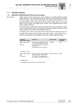
Page 80: ...te in status word 1 Meaning 0 0 24 V operation inverter not ready 1 1 Controller inhibit active 2 2 No enable 3 3 DC link is loaded 4 4 Enable 8 8 Delivery state d 13 Precharge F Error number Error in...

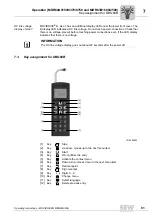
Page 81: ...uching power connections even if the LED display indicates that there is no voltage 7 3 Key assignment for DBG60B INFORMATION The DC link voltage display goes out about 20 seconds after the power off...

Page 82: ...talled in the basic unit The basic data is stored on the memory card and is always up to date If a unit has to be replaced the plant can be started up again quickly without PC and data backup by simpl...

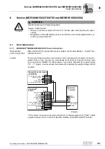
Page 83: ...e binary inputs are connected to the DC 24 V voltage supply X13 8 VO24 install a jumper between X13 7 and X13 9 DCOM DGND on the MOVIDRIVE inverter 10 minutes WARNING Electric shock due to charged cap...

Page 84: ...nses depending on the error the inverter remains blocked during the error status Immediate discon nection The unit can no longer brake the drive the output stage goes to high resistance in the event o...

Page 85: ...ode is shown in a 7 segment display The following display sequence is used e g error code 100 Following a reset or if the error code resumes the value 0 the display switches to the operating display S...

Page 86: ...ault Consult SEW Service 1 Ground fault or current converter error Ground fault in the supply cable in the regenerative power supply defective current converter Defective cable between phase module an...

Page 87: ...ine contac tor 300 Internal error Software Modul MoviLink Lib 301 Internal error Software Modul ParameterData 302 Internal error Software Modul ASMOS 303 Internal error Software Modul Utilities No res...

Page 88: ...disconnec tion 1 CRC checksum error Inverter electronics disrupted possibly due to effect of EMC or a defect Send unit in for repair 11 Power section data CRC checksum error 97 Copy error Immediate di...

Page 89: ...unit Inverter coupling uses protocol that does not match control unit Replace inverter coupling Immediate disconnec tion 13 Communication power section control unit Faulty communication with inverter...

Page 90: ...lt age No response display only 3 Supply system quality fre quency error 199 DC link charging Immediate disconnec tion open line contac tor 1 Precharging was aborted timeout Unable to charge DC link P...

Page 91: ...erial number nameplate Type designation Digits on the status label Short description of application drive application control via terminals or serial Connected components inverter etc Nature of the fa...

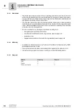
Page 92: ...units must have a copy of these operating instructions at their disposal and pay attention to the important data and notes The operating instructions must always be complete and legible 9 2 Terminolog...

Page 93: ...regeneration of electrical energy for installation into a machine for assembly with other components to form a machine MOVIDRIVE MDR60A1320 503 00 regenerative power supply units are electrical equipm...

Page 94: ...the respective appli cation SEW EURODRIVE GmbH Co KG is not liable for suitability of the indicated processes and circuit suggestions We are not liable for any damages or problems resulting from disr...

Page 95: ...current conditions within the power supply system Com mutation notches or voltage fluctuations in the supply system affect the reverse current of the unit The reverse current has to increase in case...

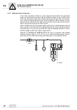
Page 96: ...ated from this section to also transmit the har monics and reactive components of the currents These conditions are met in the power supply section shown in following figure when all other consumers a...

Page 97: ...the power supply system 1 following figure If you do not follow this method of connection the inductance will prevent synchroniza tion with the power supply system and there may be a voltage increase...

Page 98: ...or too high resistance terminal connec tions D U can result in an excessive voltage drop during driving operation and an ex cessive voltage peak in regenerative operation Based on a stable power suppl...

Page 99: ...ing element for the incoming and regenerative unit The IGBTs will now route the DC link voltage directly to the consumers The resulting and almost rectangular power supply voltage supplies a current t...

Page 100: ...320 503 00 INFORMATION The same holds true for the design shown in the following figure Such a system re quires that at least each regenerative current path is equipped with a separate switch 18772014...

Page 101: ...al data MOVIDRIVE MDR60A1320 503 00 Interference immunity Meets EN 61000 6 1 and EN 61000 6 2 Interference emission with EMC compli ant installation Meets EN 61000 6 4 with NF300 503 Ambient temperatu...

Page 102: ...e Ieff Phase 100 1 min in 10 min 100 1 min in 10 min MDR60A 1320 503 00 260 A 360 A 260 A 330 A INFORMATION Just like the input of a drive controller the incoming side of the MOVIDRIVE MDR60A1320 503...

Page 103: ...are installed in the regenerative power supply unit 11 5 3 Radio interference suppression filter Install a radio interference suppression filter of category A in the MOVIDRIVE MDR60A 1320 503 00 to m...

Page 104: ...ower supply units Implement sufficient countermeasures such as separate air ducts installation of filters regular cleaning etc Do not exceed permitted range of ambient temperatures 12 1 2 Specified mo...

Page 105: ...cessary for the voltage to drop to a harmless level is determined by the drive controller in operation and has to definitely expire The specific times are given by the manufacturer for the drive contr...

Page 106: ...the regulations concerning minimum cross sections of PE conductors The effectiveness of a shielded conductor is determined by a good shielding connection a low impedance Use shields made of tin plated...

Page 107: ...0160 and EN 61800 5 1 Connect the supply cables to terminals L1 L2 and L3 of the regenerative power sup ply unit Connection always has to be three phase A certain phase sequence has to be observed fo...

Page 108: ...8 X3 PE L1 L2 L3 PE W R PE max 5 m UZ UZ Incorrect DC link connection reverse polarity ground fault will damage the connected deevices Never connect the power connectors of the inverter V U 1 2 MOVIDR...

Page 109: ...size of the connected voltage supply using the voltage selection switch prior to turning on the supply voltage following table There is also the risk of a defect in case of improper operation The tol...

Page 110: ...Use the terminal control strip X2 to connect via relay certain messages such as ready for operation or a group fault outside the unit You can also perform an external RESET or switching function via t...

Page 111: ...l Function Description X2 1 Normally closed contact Isolated relay contacts1 2 Collective fault signal switching capability of the relay contacts 30 V DC3A 230 V AC5A X2 2 Normally closed contact X2 3...

Page 112: ...gnetically impaired by the regener ative power supply units 12 4 2 Structure Establish a connection over a large area on the grounded mounting platforms for the regenerative power supply unit and radi...

Page 113: ...ield of the supply system cable directly at the drive controller on the regenerative power supply unit and the radio interference suppression filter and connect it over a large area to the mounting pl...

Page 114: ...ation of maintaining the pro tection targets required by the EMC Directive must be provided by the installer operator of a machine system When using the radio interference suppression filters provided...

Page 115: ...upply The unit is ready for operation after about 1 s 3 Check to make sure that the regenerative power supply unit is ready for operation The unit is ready for operation if only the green LED of the r...

Page 116: ...COM VO24 DGND ST11 ST12 DI DI 1 DI 2 DI 3 DI 4 DI 5 DCOM VO24 DGND ST11 ST12 1 2 3 4 5 6 7 8 9 10 11 1 2 3 4 5 6 7 8 9 10 11 Ref potential binary signals Ref potential binary signals Enable stop Enabl...

Page 117: ...tch off switch on Switch off means that control of the power semiconductors and regeneration is inter rupted and braking operation of the drive controllers is no longer possible Switch on means contro...

Page 118: ...icates the error via the centralized alarm re lay Phase failure monitoring is coded via jumpers J3 J5 J6 and J7 to the control board following table Error memory ON means that the error display Phase...

Page 119: ...ement of connections and components on the control card 1877273867 1 X3 Connection to driver board 4 X4 Connection to display board 2 X5 X8 5 LEDs display of operating status 3 X1 System synchronizati...

Page 120: ...ting up error code 3 chapter Operation and Service the reason for the disconnection is an overvoltage Phase fail ure monitoring is coded via jumpers J3 J5 J6 J7 and J8 on the control card follow ing t...

Page 121: ...eration displays of the MDR60A1320 503 00 If the binary inputs are connected to the DC 24 V voltage supply X13 8 VO24 then install a jumper between X13 7 and X13 9 on the MOVIDRIVE inverter 1877283851...

Page 122: ...ntroller via the centralized alarm relay to prevent any possible problems 15 2 1 UCE disconnection The regenerative power supply unit switches off via the UCE protective device if the max imum current...

Page 123: ...d and error can be con firmed 5 X X Unit has been turned off external OFF Enable signal required 6 X X Triggering the overvoltage monitoring Enable signal is required if the supply voltage has dropped...

Page 124: ...ating conditions Observe chapter Techni cal data page 101 15 3 1 Check cooling air vents The cooling air vents can clog up in case of unclean ambient air Check the regenerative power supply units on a...

Page 125: ...th the installation instructions for the SEW components the CE mark ing requirements for the machine system in which they are installed are satisfied on the basis of the EMC directive 2004 108 EC Comp...

Page 126: ...EN 60721 3 3 class 3K3 25 C 55 C EN 60721 3 3 class 3K3 Cooling type DIN 51751 Forced cooling temperature controlled fan response threshold 50 C Forced cooling temperature controlled fan response thr...

Page 127: ...rvice life may be reduced 25 C 70 C EN 60721 3 3 class 3K3 Cooling type DIN 51751 Forced cooling temperature controlled fan response threshold 50 C Degree of protection EN 60529 NEMA1 IP00 IP10 power...

Page 128: ...61B 16 MOVIDRIVE MDR60A 61B unit series sizes 2 to 7 Technical Data Basic Unit 16 3 MOVIDRIVE MDR60A 61B unit series sizes 2 to 7 The following figure shows MOVIDRIVE MDX61B regenerative power supply...

Page 129: ...n a power connection terminal and an obstruction toward which the wire is directed on leaving the terminal must correspond with the minimum values given in the table below Cable cross section in mm2 S...

Page 130: ...ink VDC at nominal supply current Isupply DC 560 V 780 V Nominal DC link current IZK at nominal supply current Isupply DC 35 A DC 70 A Max DC link currentIDCL_max DC 53 A DC 105 A GENERAL INFORMATION...

Page 131: ...wer SA at Vsupply 3 AC 380 500 V 90 kVA 175 kVA DC link VDC DC 560 V 780 V Nominal DC link current IZK at nominal supply current Isupply DC 141 A DC 324 A Max DC link currentIDCL_max at nominal supply...

Page 132: ...ommended line fuse 175 A 500 A 1 The listed technical data applies to units with series no DCV200xxx For units of the previous series with no DCV185xxx refer to the provided documentation and the data...

Page 133: ...CL_max at nominal supply current Isupply DC 382 A DC 610 A Max continuous DC link current IZK_Dmax at nominal supply current Isupply DC 318 A DC 508 A GENERAL INFORMATION Power loss at PNPVmax 5000 W...

Page 134: ...Data Basic Unit 16 8 Dimension drawings 16 8 1 MOVIDRIVE MDR60A0150 size 2 Observe the following minimum clearance for control cabinet installation Above and below 100 mm 3 9 in No clearance required...

Page 135: ...it 16 8 2 MOVIDRIVE MDR60A0370 size 3 Observe the following minimum clearance for control cabinet installation Above and below 100 mm 3 9 in No clearance required on the side 1454310923 All dimensions...

Page 136: ...learance for control cabinet installation Above and below 100 mm 3 9 in Do not install any components that are sensitive to high temperatures within 300 mm 11 8 in above the unit for example contactor...

Page 137: ...s within 300 mm 11 8 in above the unit for example contactors or fuses No clearance required below 70 mm 2 8 in on the side 1454342923 All dimensions in mm in 1 3 2 SKS L1 L2 L3 off collective error p...

Page 138: ...nimum clearance for control cabinet installation Above 100 mm 3 9 in Do not install any components that are sensitive to high temperatures within 300 mm 11 8 in above the unit for example contactors o...

Page 139: ...ative for compiling the technical documents 6 852 5 9 PE R UQVW OLFNOH 6WUD H UXFKVDO GHFODUHV XQGHU VROH UHVSRQVLELOLW WKDW WKH UHJHQHUDWLYH SRZHU VXSSO XQLWV RI WKH VHULHV 029 5 9 0 5 029 5 9 0 5 DU...

Page 140: ...60B Basic displays 80 Functions of the keys 81 DC link adapter 2Q 48 DC link adapter 4Q DLZ14B 49 DC link coupling DLZ11B 51 DC link coupling DLZ31B 53 DC link voltage 68 Declaration of conformity MOV...

Page 141: ...ntroller 71 Inverter status 68 IT system device Converting MDR60A0150 39 Converting MDR61B1600 2500 40 L LED signals 123 Line voltage 72 M Mains off tolerance time 72 Manual reset 75 Memory card 82 Mi...

Page 142: ...x Current reference signal 73 P430 Current reference value 73 P431 Hysteresis 73 P432 Delay time 73 P433 Signal 1 if 73 P6xx Terminal assignment 73 P60x Binary inputs of basic unit 73 P600 Binary inpu...

Page 143: ...52_ 59 Status displays 68 Structure MDR60A0150 Size 2 15 MDR60A0370 Size 3 16 MDR60A0750 size 4 17 MDR60A1320 size 6 18 MDR61B1600 2500 size 7 19 T Technical data MDR60A regenerative power supply unit...

Page 144: ...144 Operating Instructions MOVIDRIVE MDR60A 61B Index connection type A 32 DC link connection without MDR60A 61B in connection type B 33 Signal terminals 38 Work 69 0 9 7 segment display 85...

Page 145: ......

Page 146: ......

Page 147: ......

Page 148: ...URODRIVE Driving the world SEW EURODRIVE Driving the world www sew eurodrive com SEW EURODRIVE GmbH Co KG P O Box 3023 D 76642 Bruchsal Germany Phone 49 7251 75 0 Fax 49 7251 75 1970 sew sew eurodrive...

Reviews: