Operating Instructions – MOVIDRIVE® MDR60A/61B
79
7
Operating displays
Operation (MDR60A0150/0370/0750 and MDR61B1600/2500)
7.2
Operating displays
7.2.1
MOVIDRIVE
®
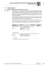
MDR60A0150/0370/0750 operating displays
Ready signal
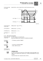
Supply system failures (affecting one or more phases) are detected within one supply
system half-wave. The regenerative function is inhibited and the ready signal revoked.
The return supply voltage is also detected within one supply system half-wave. It is fed
back automatically into the supply system after a switch-on delay of 200 ms. The ready
signal is then set again. The supply system rectifier of the regenerative power unit al-
ways remains switched on.
The ready signal is revoked when a thermal overload occurs in the regenerative power
unit or in case of power failure. This ready signal must be evaluated in order to provide
thermal protection for the regenerative power supply unit.
A braking resistor must be connected to the inverter to be able to bring the drives to a
controlled stop in case of an interruption in the power supply or power failure. This re-
sistor is only energized during braking when there is a power supply interruption.
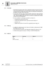
Unit status/
supply system status
Response
Ready signal
Ready signal
indicator
Supply system failure
or
Unit fault
→
MDR60A not ready
Power failure is detected under load
within one supply system half-wave.
Immediate inhibit of the regenerative
power supply
Input rectifier remains switched on.
Not ready
Red
Supply system OK again
and
no unit fault
→
MDR60A ready
Supply system O.K. is detected within
one supply system half-wave. After
200 ms delay
1)
, the regenerative
power supply is started automatically.
1) ensures safe operation in the event of contactor chatter
Ready after 200 ms Yellow


