MOVITRAC
®
31.. PROFIBUS Fieldbus Interface
3 1
The PROFIBUS-DP
Interface
3
3 .6
Control via PROFIBUS-DP
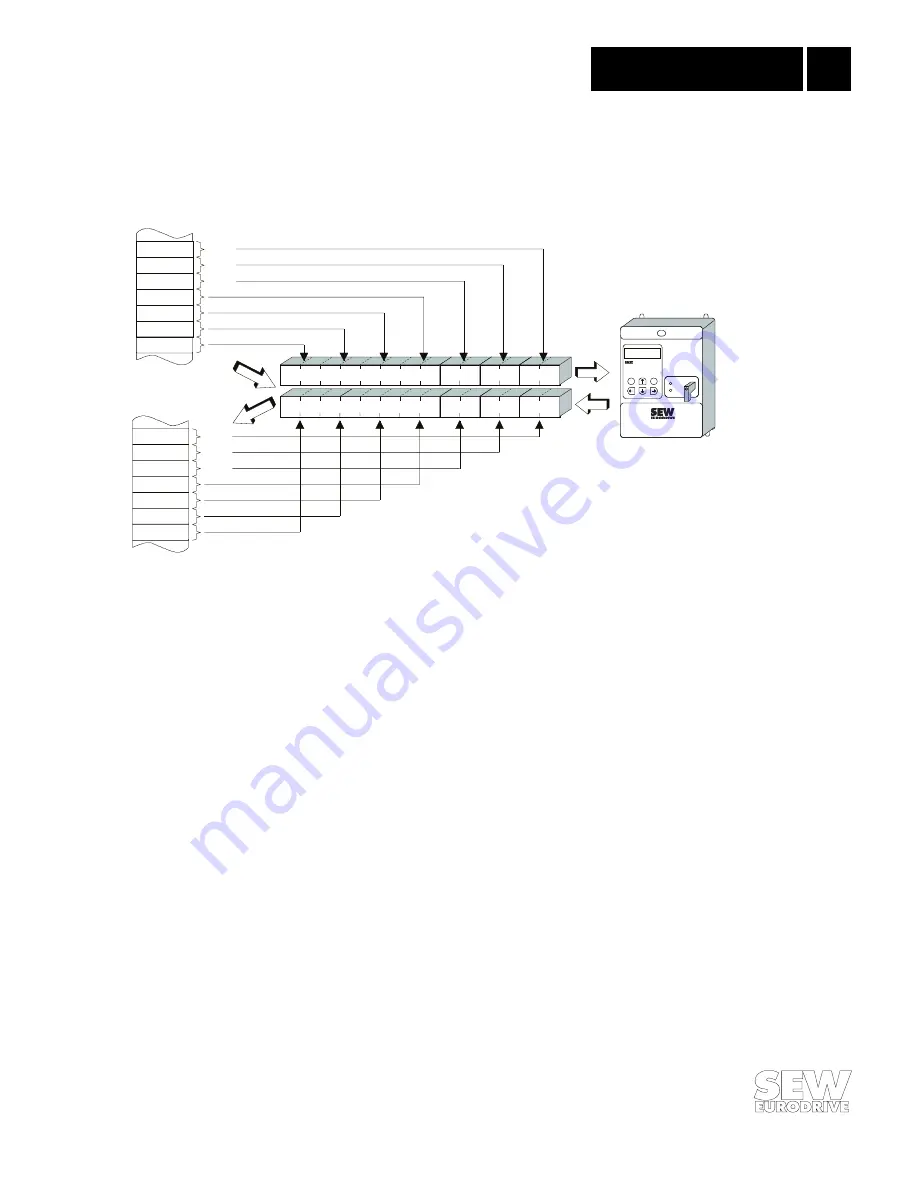
The inverter is controlled via the process data channel, which can be one, two or three I/O words in
length. These process data words are, for example when a programmable logic controller is being
used as DP master, stored in the I/O or peripherals area of the controller and can thus be
addressed in the usual manner (Fig. 37).
00950AEN
Fig. 37: Allocation of the PLC I/O area
While the process input data (actual values) are being read, e.g. using the Load command in the
case of Simatic S5, the process output data (setpoints) can be sent using the Transfer commands.
Referring to Fig. 37, Example 1 shows the syntax for handling the process input and output data of
the MOVITRAC
®
31.. inverter. The factory setting for the process data channel is shown as a
comment.
Example 1:
Inverter control via the process data
L IW 50
Load PD1 (status word 1)
L IW 52
Load PD2 (speed actual value)
L IW 54
Load PD3 (no function)
L KH 0006
T OW 50
Write 6hex to PD1 (control word 1 = enable)
L KF +1500
T OW 52
Write 1500 dec to PD2 (speed setpoint = 300 1/min)
L KH 0000
T OW 54
Write 0 hex to PD3 (no function,
sent value without effect)
For details of the control via the process data channel, in particular the coding of the control and
status words, please refer to the
Unit Profile User Manual.
MO
VIT
RAC
®
841
E
Q
RUN
BUS
FAULT
AW 54
AW 52
AW 50
AW 48
AW 46
AW 44
AW 42
EW 54
EW 52
EW 50
EW 48
EW 46
EW 44
EW 42
PD 3
PD 2
PD 1
PD 3
PD 2
PD 1
PD 1
PD 2
PD 3
PD 1
PD 2
PD 3
Parameter channel
Parameter channel
PLC address area
FIELDBUS
CONTROL MODE
Phone: 800.894.0412 - Fax: 888.723.4773 - Web: www.clrwtr.com - Email: [email protected]


