


Manual – MOVIDRIVE® MDX61B MOVI-PLC® DHP11B Control Card
47
6
Features of the SEW DP-V1 interfaces
DP-V1 Functions
6.2
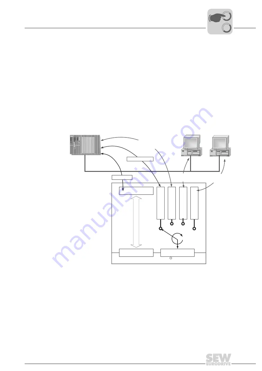
Features of the SEW DP-V1 interfaces
The SEW fieldbus interfaces to PROFIBUS DP-V1 have the same communication fea-
tures as the DP-V1 interface. The DHP11B control card is usually controlled via a C1
master with cyclical process data in accordance with the DP-V1 standard. This C1 mas-
ter (usually a PLC) can also use an 8-byte MOVILINK
®
parameter channel during cycli-
cal data exchange to execute the parameter services with the DHP11B control card. The
read
and
write
services allow the C1 master access to connected stations via the DP-V1
C1 channel.
Parallel to these two parameter channels, a further two C2 channels can be set up. For
example, the first C2 master (visualization) reads the parameter data, and the second
C2 master (notebook) configures the DHP11B control card using the MOVITOOLS
®
software.
20069AXX
Figure 18: Parameter channels for PROFIBUS DP-V1
Cyclic IN/Out
Process Data
MOVI-PLC
DP
Paramete
rbuffer
Parameterbuffer
cyclic
SEW
PROFIBUS
DP-V1
Interface
C1-Parameterbuffe
r
C2-Parameterbuffe
r
C2-Parameterbuffe
r
Acyclic DP1-V1
C1-Services
DP:
DP:
C1-Master
C2-Master
C2-Master
Acyclic DP1-V1
C2-Services
PROFIBUS DP-V1
Acyclic DP1-V1
C2-Services
8 Byte Param
PD
R
0
0
I


