Sesamo PROSWING Operating Instructions Manual Download Page 31

6. Press push buttons [

+

] e [

-

] until 

LP

appears; press [

ENT

] until [

--

] appears; press again[

ENT

] for 5 seconds; when

disappears [

--

] release push button [

ENT

].

7. Door will start learning cycle, opening direction.

ATTENTION: 

when door reaches desired opening position, stops door in that position: this position will be memori-

zed as max opening. Immediately after, door will close completely at slow speed with display 

CL

blinking. 

When door is in closed position and 

CL

stop blinking, it is possible to check functioning pressing [

ENT

]: door has to

open and close regulary.
During the functioning, max opening angle is reduced as a factory setting. This parameter is modificable through
software MillenniumWare (advanced parameter 

→ % reduction opening angle)

.

First cycle (opening/closing), after (RESET) will be at slow speed.
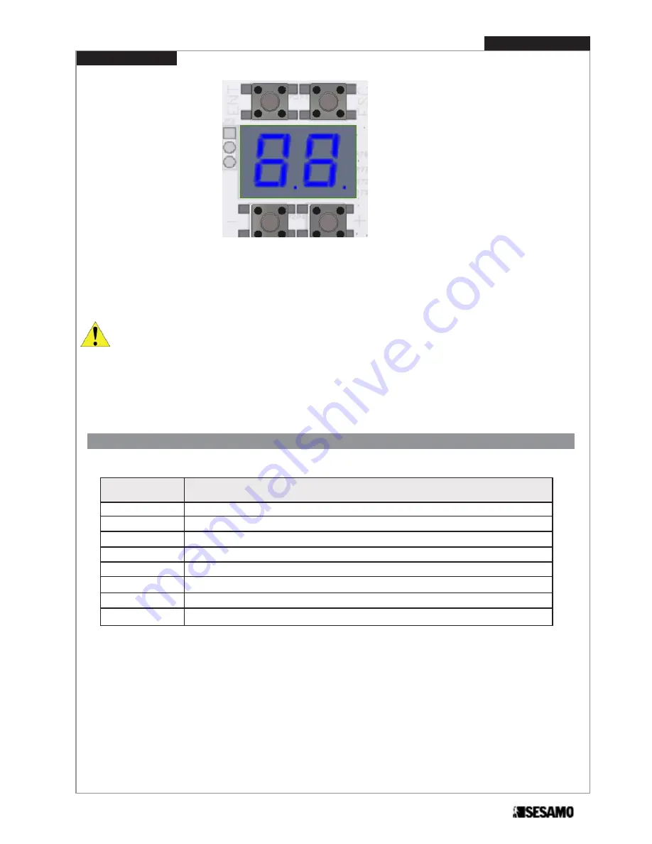
ESC

ENT

+

_

Fig. 32

31

PROSWING(M)

Operating instruction

Code

Description

OP

Fixed

Door opened

OP

Blinking

Door opening

CL

Fixed

Door closed

CL

Blinking

Door closing

E1

Door needs self learning procedure (see Paragraph “Start up”)

E2

Wrong arm selected (DIP 1), or wrong selection automatism (DIP 5)

E3 / E4

Over Current

E8

NO encoder.

Display are also used to show message or error code:

Message or errors code

Summary of Contents for PROSWING

Page 1: ...Automatic Operator for swinging doors O P E R A T I N G I N S T R U C T I O N S PROSWING m ...

Page 2: ...PROSWING M Operating instruction 2 ...

Page 3: ... base holes positioning pag 13 Pull arm installation pag 14 Push arm installation pag 18 Preliminary checking pag 21 Wiring power supply pag 22 Control board Proswing M pag 22 Wiring pag 23 External peripherals connectors Input pag 24 External peripherals connectors Output pag 25 Dip switches setting pag 26 Parameters adjustment display pag 27 Start up pag 30 Message or errors code pag 31 Operatin...

Page 4: ...c pag 35 Wiring and use for double Proswing pag 36 Inter lock wiring and use pag 39 Installation batteries OPTIONAL pag 40 Logic switch pag 42 Connector for PC Unit connections pag 42 Delivery modality pag 42 SESAMO reserves the right to change the technical specifications of the products even without notice ...

Page 5: ...r with the use manual and all the information requi red for correct use in automatic and manual modes even for electronic locking and in the event of emergency Pay careful attention to the messages in this manual that are marked with the hazard symbol They can either be warnings aimed at avoided potential equipment damage or specific signals of potential hazard to the installer and others This dev...

Page 6: ...monitoring opening and or closing path is an option to consider after risk assessment evaluation Power supply 230V 10 ac 50 Hz Nominal power 85 W Nominal motor torque 45 Nm External device power 12Vdc 12W max Emergency battery power 24V 1 3 Ah Opening time 3 6 sec 70 s 20 s Closing time 4 15 sec 40 s 10 s Max opening angle 110 Wing dimension 700 1400 mm Working temperature Inside automatsm from 10...

Page 7: ...possible dangerous areas from mechanical risks during movement as anticras hing conveying shearing 12 For mainteinance use only genuine SESAMO spare parts 13 Do not modify components that belongs to the whole automatism 14 The installer must supply end user all the informations in case of manual operating in emergency 15 End user shall refrain from any attemp to repair or direct intervenction and ...

Page 8: ...eed door weight and width as shown in the diagram in technical specification paragraph To each type of arm correspond a different type of jamb dimension do not exceed this value see Paragraph arm installa tion This device is intended only for swinging pedestrian door dry and inside use SESAMO shall not be held liable for any other use contrary to the use foreseen RIGID PULL ARM ARTICULATED PUSH AR...

Page 9: ...he door opening STANDARD PUSH ARM The pushing arm can be fitted PUSH it is used when the automatism is installed on the opposite side of the door opening LONG PUSH ARM The long push arm can be fitted PUSH it is used when the automatism is installed in the opposite side of the door opening jamb depth 0 150 mm jamb depth 150 300 mm jamb depth 50 100 mm Fig 1 Fig 2 Fig 3 9 PROSWING M Operating instru...

Page 10: ...ions Arm extensions ATTENTION For a correct positionning refer to arm installation paragraph L 50 mm L 70 mm L 90 mm Fig 4 L 30 mm standard Fig 5 56 130 664 86 94 17 630 17 PROSWING M Operating instruction 10 ...

Page 11: ...d the weight of the automatism as well the hinges also check to not have friction between fixed and mobile parts use proper equipment and tools to install in security and in accordance with the regulations Automatism Fixing REF DESCRIPTION A Cover fixing screws B Aluminum cover C Control board fixing screws D Control board E Gear motor fixing screws F Gear motor G Transformer fixing screws H Trans...

Page 12: ...and remove gear motor 6 unscrew screws Fig 6 part I and remove end caps Fig 6 part M ed L 7 fix aluminium base Fig 6 part N to thre structure following instructions of the following paragraphs dipending on arm type 8 reassemble all components but end caps and aluminium cover ATTENTION to make easier reassembling gear motor partially screw the screws Fig 7 part E then lean gear motor on to them Ins...

Page 13: ... in the paragraph concerning the type of arm selected Fig 8 With double automatism prearrange the conncetion wiring between the two single automatisms 84 76 88 202 234 30 Aluminum base holes positioning 19 5 19 5 22 5 22 5 Fig 9 84 76 88 202 234 30 19 5 19 5 22 5 22 5 hinge axis hinge axis 13 PROSWING M Operating instruction ...

Page 14: ... same side of door opening ATTENTION For a correct positionning always refer to the hinge axis and gear motor axis as shown in Fig 10 e 11 Door opening RIGHT see Fig 11 Door opening LEFT see Fig 10 Fig 10 Hinge axis Pull arm Sliding guide Gear motor axis 600 180 C 200 Fig 11 AHinge axis Pull arm Sliding guide 600 180 C 200 Gear motor axis ...

Page 15: ...oupling bolt of the arm with the cylindric skid have not to create force in opening closing cycle A positioning error of the automa tism might create bending bet ween the bolt of the pulling arm and the cylindric skid more than the allowed tolerance damage parts of the automatism 32 ARM EXTENSION DIMENSION C Arm extension standard 35 Arm extension L 50 mm 55 Arm extension L 70 mm 75 Arm extension ...

Page 16: ...x guide profile horizontally to the door following dimensions shown in Fig 12 P O I Fig 13 4 Insert washer Fig 14 part B and screw Fig 14 part C into arm extension Fig 14 part A 5 Insert arm Fig 14 part D in the arm extension slot and tight screws Fig 14 part E A B C D E Fig 14 PROSWING M Operating instruction 16 ...

Page 17: ...lightly open door 8 Rotate arm until reaching skid Fig 15 part F 9 Screw skid shaft Fig 15 part F into the arm Fig 15 part Q 10 Insert guide cover profile Fig 15 part I 11 Insert right end cap Fig 15 part M and the left end cap Fig 15 part N onto the guide with their screws Fig 15 part L I F L N O P M Fig 15 Q Verify the dimension about 15 mm Fig 16 Fig 16 15 mm 17 PROSWING M Operating instruction...

Page 18: ...g 18 Fig 17 Hinge axis Door bracket Motor reducer axis 200 Fig 18 Push arm installation Push arm is used when automatism is installed on the opposite side of door opening ATTENTION For a correct positionning always refer to the hinge axis and gear motor axis as shown in Fig 17 e 18 PROSWING M Operating instruction 18 ...

Page 19: ...mm 28 Arm extension L 70 mm 48 Arm extension L 90 mm 68 Fig 20 OPENING DIRECTION Push arm Door bracket 56 Motor axis Jamb lower edge ATTENTION final tightening of the screws must be perfored only after checking arm can easily rotate under door jamb Fig 20 E Increasing jamb depth maximum opening angle is proportionally reduced 25 Jamb depth 0 300 mm ...

Page 20: ...ews M8 x 16 Fig 21 part G 4 Fix door bracket Fig 24 part F to the door following dimension shown in Fig 19 e 20 5 Insert arm extension Fig 21 part A into gear motor shaft 6 Tight screw Fig 21 part C until arm extension part 1 is well fixed to gear motor shaft 7 Keeping door closed rotate arm as show in Fig 22 and tight screws M8 x 16 Fig 21 Part G Fig 21 A B C E D F G Fig 22 Fix PUSH ARM to the do...

Page 21: ...ollows Remove carefully dust or any other residual of the installation Verify automatism being well fixed Verify all screws well tighten Verify all wiring well fixed and not near moving parts Verify arm well fixed to door 21 PROSWING M Operating instruction ...

Page 22: ...rs as shown in Fig 23 ATTENTION Never invert power supply cable and ground cable Power suppply must be isolatable from the general panel with a bi polar switch with minimum contact opening equal to 3 mm not supplied Control board PROSWING M Fig 24 shows the main electronic components connection of the control board 230V AC Fig 23 Fig 24 Base or advanced selector connector Motor connector Electric ...

Page 23: ...truction PROSWING M 23 Fig 25 Connect the following terminal boards logic switch Fig 25 part A ON OFF switch Fig 25 part B transformer Fig 25 part C motor Fig 26 part D encoder Fig 26 part E Wiring B C A Fig 26 D E ...

Page 24: ...toring opening cycle If the door is opening and the contact closes the control board gives a stop command immediately Opening will only continue after this signal is disactivated The signal must be short circuited with COM if no devi ce is connected SAFE CLOSE NC Closing safe contact for safety sen sors monitoring closing cycle If the door is closing and the contact opens the control board gives a...

Page 25: ... B A OUT 15 Vdc NO Normally Open NC Normally Closed All the input have to be referred to COM SIGNAL TYPE DEFAULT DESCRIPTION FUNCTION AUX OUT 1 e 2 Auxiliary output contact that can be set as follows 0 Monitoring sensors It monitorins safety sensors 1 Inter lock To be connected to the input interlock of the other automa tism to obtain interlock logic 2 Door opened It signals door in opened positio...

Page 26: ... after automatism RESET DipSwitch Parameter Setting Factory setting 1 ARM SELECTION OFF push arm ON Pull arm OFF 2 LOW ENERGY mode OFF Normale ON Low Energy OFF 3 PUSH GO OFF disabled ON enabled OFF 4 KEY OPERATING OFF Monostable on Bistable OFF 5 OFF OFF 6 BATTERY MODE OFF Continuos working ON Open door OFF 7 BATTERY SETTING OFF Battery not installed ON Battery installed OFF 8 Not used OFF ...

Page 27: ...on Adjustment DEFAULT setting 01 Opening speed RANGE 20 s 70 s step of 5 s 60 02 Closing speed RANGE 10 s 40 s step of 5 s 30 03 Idle time RANGE 0 60 sec step of 1 second 0 04 Idle time in Low Energy RANGE 5 60 sec step of 1 second 5 05 Force in closing position RANGE 0 9 0 no force 9 max force 5 06 Anticrushing RANGE 1 9 It is applied both for opening and closing 1 more sensitive 9 less sensitive...

Page 28: ... Ripetizione comando serratura 0 18 Auxiliary output configuration 2 0 Monitoring of the sensors 1 Interlock 2 Stop open condition 3 Stop closed condition 4 Failure 5 Ripetizione comando serratura 1 19 MultiMaster 0 No managing Multimaster 1 15 Keynote for MultiMaster connections 0 20 Opening safety sensor exclusion Angle opening safety exclusion RANGE 0 40 of total angle opening 30 21 Phase displ...

Page 29: ...test 0 No Test 1 Ciclycal 2 Ciclycal fast 0 Sd Set to default 1 Select command with buttons e 2 Press ENT 3 Display 4 Press again ENT for 5 seconds to confimr 5 When disappears release ENT Lp Learning cycle 1 Select command with buttons e 2 Press ENT 3 On display 4 Press again ENT for 5 second to confirm 5 When disappears release ENT During parameters setting any movement of motor is allowed When ...

Page 30: ...3 Switch in ON position 1 4 Check display is lit and that E1 is shown on dislay if E2 appears check arm setting 5 If necessary set jumper to correctly see diplay see Fig 31 Start up Fig 29 Fig 30 DipSwitch Parameter Setting 1 ARM SELECTION OFF push arm ON Pull arm 5 OFF AUTOMATISM FOR RIGHT OPENING AUTOMATISM FOR LEFT OPENING Hinge axis Hinge axis jumper jumper Fig 31 PROSWING M Operating instruct...

Page 31: ...ng pressing ENT door has to open and close regulary During the functioning max opening angle is reduced as a factory setting This parameter is modificable through software MillenniumWare advanced parameter reduction opening angle First cycle opening closing after RESET will be at slow speed ESC ENT _ Fig 32 31 PROSWING M Operating instruction Code Description OP Fixed Door opened OP Blinking Door ...

Page 32: ...ng logic Manual START 1 and START 2 are not monitored Open and close only through push button on selec tor or low energy or manually pushing the door 1 radar Exit only radar only the input START 2 of the electronic control card is monitored A signal ori ginating from a sensor connected to this input triggers the opening and consequent closing of the door doors The electric locking system if presen...

Page 33: ...arameter 11 see paragraph Parameters adjustment display Parameter 11 has different meaning and range depending on type of lock used It is possible to adjust last final closing force to facilitate closing with impulsive locks set through parameter 12 paragraph Parameter adjustment display It is possible to use aux input contact as a lock activation pulse working in parallel with automatic function ...

Page 34: ...ameter 14 and confor ming to the logic selected on selector FAIL SAFE LOCK Parameter 10 3 MOTORIZED LOCK Parameter 10 4 IMPULSIVE LOCK WITH RESTTORE AT POWER CUT OFF Pameter 10 5 BACK HIT LEGEND START OPENING START CLOSING DOOR CLOSED voltage lock voltage lock voltage lock 100 1000 Parameter 11 Parameter 11 Parameter 11 command command ...

Page 35: ... presence 15V If off check For mains voltage That fuse is not interrupted Use the four conductors in the shielded wire for connections observing the correspondences indicated by the markings on the terminal board and multi logic selector Do not connect the shield of the wire used For further information on multi logic selector use see the instructions for use External peripheral power connector 15...

Page 36: ...e door see Fig 45 For solution 2 proceed as follows 1 remove all components on both automatisms in order covers end cap control boards motor gears transformers 2 put the two aluminum base and the central joining base on a plane surface Fig 34 3 insert each base under the tongue of the two joining parts as showed Fig 35 ATTENTION Maintain the orientation of the aluminum bases as shown in Fig 46 so ...

Page 37: ...Even in case of door without displacement it is necessary to set Master and Slave ATTENTION use same power line for the two automatisms without any fuses or switches Peripherals command SAFE CLOSE KEY START 1 e START 2 have to be connected to Master door SAFE OPEN command have to be connected separately on each control boards Fig 34 Hinge axis SX Hinge axis DX PROSWING ON RIGHT PROSWING ON LEFT PA...

Page 38: ...light displacement is enough but in closing where it is important to be sure to close on the right overlapping an higher delay between the two doors is needed If there is no overlapping set on MASTER parameter 21 0 and parameter 22 0 If there is overlapping set on MASTER parameter 21 and parameter 22 more than 0 3 To set in function automatisms follow Start up paragraph procedure considering that ...

Page 39: ...rd without priority COM Use 4x0 22 shielded cable do not connect shield Set priority for opening in case of simultaneous command through parameters 15 and 17 set parameter 15 2 on board with priority set parameter 17 1on board with priority set parameter 15 3 on board without priority set parameter 17 1 on board without priority In this way in case of simultaneous command will open Master as a fir...

Page 40: ...ble To install power kit batteries proceed as follows 1 Fix the sponge A as shown in Fig 39 using as reference the aluminum base profile bottom line 2 Insert the two batteries C in the supporting metallic bracket B and fix the whole assembling through screw M6x10 D 3 Connect cables as shown in Fig 40 ...

Page 41: ...les as shown in Fig 41 F and G 5 Connect the batteries cables terminal board to control board Fig 42 H 6 Insert control board for batteries I on main control board Fig 43 7 Set dip switch 7 ON and dip switch 6 OFF if it is required continuous use after power failure or ON if it is requi red stop open after power failure Fig 44 Fig 44 41 PROSWING M Operating instruction ...

Page 42: ...the PROSWING unit to a Personal Computer The following is pos sible with MILLENNIUM WARE software Advanced adjustments of some operating parameter Diagnostic and advanced information on status Microprocessor programming PC connection board Connector for PC unit connections Close the automatism s cover and tight screws Hand the guarantee and test certificate over filled according to the instruction...

Page 43: ...SESAMO srl Str Gabannone 8 10 15030 Terruggia AL Italy Tel 39 0142 403223 Fax 39 0142 403256 www sesamo eu E mail info sesamo eu PROSWING m MAN_PRO M_EN_0_02_12 ...

Reviews: