


SerVision
MVG400 Installation Guide
Installing the MVG400 System
11
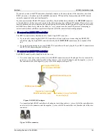
2. Place the unit in the desired location and attach it securely by connecting the side supports to the anchoring
surface with two or three screws on each side. (These screws are not included with the MVG400.)
Note:
The unit can be placed horizontally or vertically. If it is placed vertically, the left side (the side
containing the hard drive) should face up.
Figure 7: Hard-drive compartment
Diagram of the Rear Panel
The rear of the MVG400 unit contains the connectors described below.
Figure 8: MVG400 connectors
Power
Audio Out (Aout)
Audio In2 (Ain2)
Audio In1 (Ain1)
TV Out
Ethernet
Cable
Video In
Vin1–Vin4
RS232/485
USB Port
12VDC Power Out
Sensors
In1–In4
Activators
Out1, Out2
GPS Antenna
Ethernet
In
Ethernet
Out
WiFi
Antennas
Hard-drive compartment


