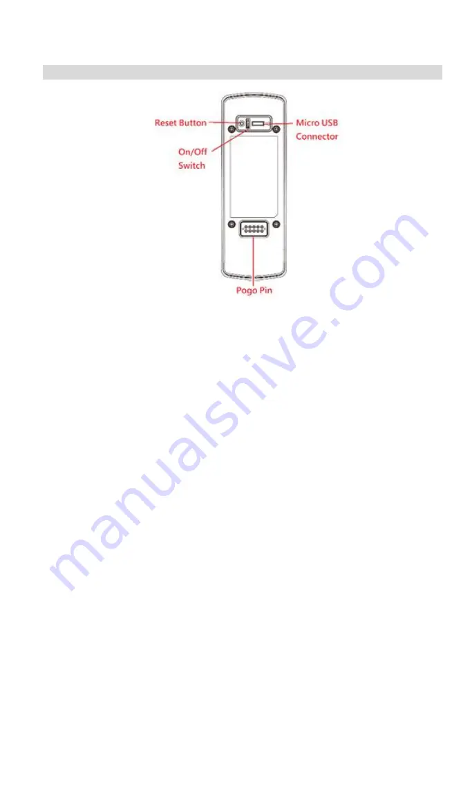
Sercomm DBC831V2 Setup Manual Download Page 6

Rear Panel 


Reset Button 

When pressed and held over 10 seconds, the LED will be solid 
amber, which means the settings of camera will be set to their 
default values. 

On/Off Switch 

Use this switch to turn on/off the device. 

Micro USB Connector 

This connector is used for charging the power. Connect the 
supplied Micro-USB cable to this port. 


Summary of Contents for DBC831V2

Page 1: ...DBC831v2 Wireless FHD Doorbell Camera Setup Guide Copyright 2018 All Rights Reserved Document Version 1 0...

Page 2: ...ter 2 Setup 6 System Requirements 6 Installation 6 Chapter 3 Hardware Installation 10 Overview 10 Power Kit Installation 13 Always On Bracket Installation Optional 14 Battery Pack Installation Optiona...

Page 3: ...orbell Camera features components and capabilities Package Contents The following items should be included If any of these items are damaged or missing please contact your dealer immediately 1 Doorbel...

Page 4: ...2 5 Power Kit x 1 Foam tap x 1 Twist splice wire connector x 2 6 Always On Bracket x 1 Optional may not included in the package 7 Battery Pack x 1 Optional may not included in the package...

Page 5: ...of Battery Pack can only be charged 0 to 35 85 RH Max and discharged 20 to 50 85 RH Max Front Panel Light Sensor This is hardware sensor to detect LUX Microphone The built in microphone is useful for...

Page 6: ...LED will be solid amber which means the settings of camera will be set to their default values On Off Switch Use this switch to turn on off the device Micro USB Connector This connector is used for c...

Page 7: ...t flashing amber indicating doorbell camera is trying to connect to your Wi Fi network in PBC mode WPS Failure Amber Solid 5s If doorbell camera falls during WPS enrollment the LED will be solid on fo...

Page 8: ...side of the doorbell camera and wait for 20 seconds until the LED turns to flashing amber Note The internal battery supports about 40 minutes of operation If you don t see the camera powering up pleas...

Page 9: ...econds the Doorbell Camera will be in the WPS Pin Code mode Please make sure if your AP or router support the WPS Pin code mode Note Once Doorbell ever connected to AP by WPS or GUI configuration then...

Page 10: ...e configured while using IE browser Other browsers can just view the video rather than configuration g Video will start playing automatically There may be a delay of a few seconds while the video stre...

Page 11: ...doorbell produces an electronic sound that is programmable and comes in the form of a unique sound it s a digital chime If it has a traditional ding dong sound it s a compatible analog chime 4 Comple...

Page 12: ...ote For DBC831v2 installation doorbell must be attached with indoor chimer and transformer use for power supply loop While mounting regular bracket it must use 8 24V transformer to power up doorbell w...

Page 13: ...the bracket with screws Note Install the anchors if necessary The provided lever can be used for measuring angles to prevent inclination 7 Attach the doorbell camera to the mounting bracket Make sure...

Page 14: ...12 8 Turn on the breaker circuit 9 Check that the chime is working normally by pushing the doorbell button If the AC wires are not connected properly the LED will blink amber every 5 seconds...

Page 15: ...1 Turn off the circuit breaker for the indoor chimer 2 Remove the cover from the indoor chimer 3 Loosen the Front and Trans terminal screws on the indoor chimer 4 Connect white wire from the Power Ki...

Page 16: ...the doorbell camera will be in always on mode which brings back the 5 second pre buffer connects live view faster and removes the need for the internal battery to be charged 1 Use the always on brack...

Page 17: ...unting bracket should lay flat against the wall Over torqueing can warp the bracket and cause it to lose contact with pins Specification LED LED x 1 Green Waterproof Enclosure IP65 Pogo Pin 2 x 4 8 Pi...

Page 18: ...nstall the plate onto the wall 2 Align the four square pegs with the slots on the mounting plate Insert the pegs into the slots and slide the battery pack downward until you hear a clicking sound 3 At...

Page 19: ...LEDs Slide Switch Activity LED Color LED Intensity LED Behavior Description Turn On Red Orange Green Medium Solid After turning on the switch LED color will be on for three seconds then turn off The...

Page 20: ...50 C Always On Bracket mode 20 C to 40 C Day Mode 20 C to 35 C Night Mode Storage Temperature 20 C to 45 C Network Protocols TCP IP HTTP HTTPS DHCP uPnP NTP RTP RTCP RTSP DN Wireless 802 11 b g n IR L...

Page 21: ...TV technician for help To assure continued compliance any changes or modifications not expressly approved by the party responsible for compliance could void the user s authority to operate this equipm...

Page 22: ...20...

Reviews: