Sera 409.2 ML Series Operating Instructions Manual Download Page 27

Multi-layer diaphragm pump


Serie 409.2 ML


Operating instruction 


TA  431 

Rev. 

8  en 

06/2015 

Technical modifications reserved! 

www.sera-web.com 

27 


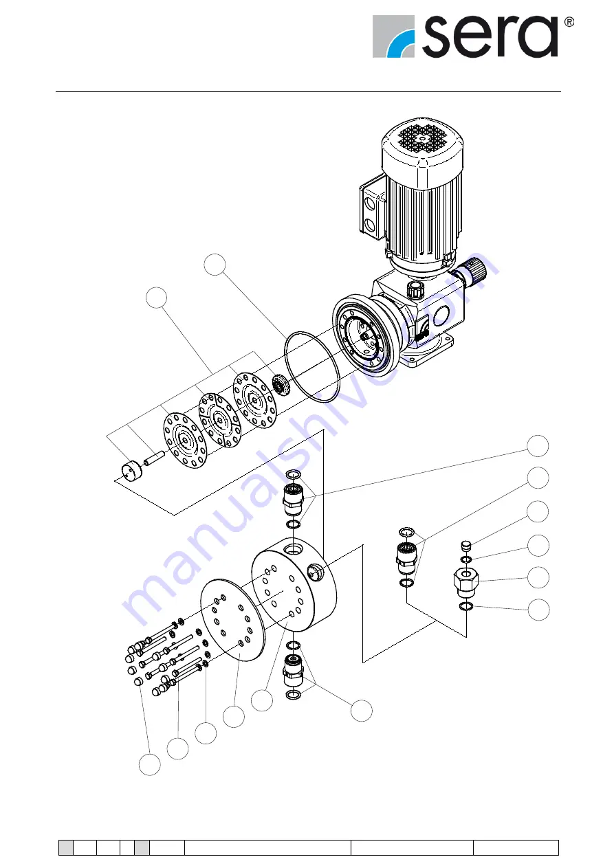
10.3  Spare- and wearing parts 


...409.2 –   11 ML 

...409.2 –   17 ML 

...409.2 –   30 ML 

...409.2 –   45 ML 

...409.2 –   72 ML 

...409.2 – 110 ML 

...409.2 – 150 ML 

...409.2 – 220 ML 


Fig. 34   Spare- and wearing parts 

11 

12 

13 

14 

10 

1.1 

1.2 

1.3 

1.4 

1.5 

1.6 

Summary of Contents for 409.2 ML Series

Page 1: ...a v a i l a b l eu n t i l 3 1 1 2 2 0 1 6...

Page 2: ...nt 12 7 2 3 Assembly pump 14 7 2 4 Pump body 15 7 2 5 Suction Pressure valve 15 7 2 6 Stroke frequency transmitter optional 15 7 2 7 Diaphragm rupture monitoring 16 7 3 Driving motor 17 7 3 1 Motor co...

Page 3: ...sera web com 3 13 Foreseeable misuse 34 13 1 Transport 34 13 2 Assembly and installation 34 13 3 Start up 34 13 4 Operation 34 13 5 Maintenance Repair 34 13 6 Cleaning 35 13 7 Shut down 35 13 8 Disas...

Page 4: ...p ML Execution Multi layer diaphragm 2 2 Type plate Each sera multi layer diaphragm pump is factory provided with a type plate The following information can be found on this type plate 1 2 3 4 5 6 7 F...

Page 5: ...used conveying media 3 2 Marking of instructions 3 2 1 Marking of instructions operating manual Special notes in these operating instructions are marked with the general danger symbol safety symbol a...

Page 6: ...he machine are only allowed after previous agreement of the manufacturer Original spare parts and accessories that are authorized by the manufacturer are essential for safety reasons CAUTION Use of ot...

Page 7: ...adapted to the weight of the pump and attach it to the motor flange of the pump see Fig 02 Fig 02 Transport Handling 4 3 Storage An undamaged packaging protects the device during subsequent storage a...

Page 8: ...ustrated Actuator for Ex area pneumatical actuator EExeIIT4 Driving motor Blind plug Driving motor for operation Driving motor M Execution with frequency converter mounted frequency converter manual s...

Page 9: ...ications reserved www sera web com 9 zum Abnehmen der Stellmotorhaube min 200 H2 H3 B A C E F D 148 K1 K2 K3 K 4 6 H1 DN 10 75 154 M 1 4 21 N 1 4 7 80 98 98 80 30 39 M8 d 6 5 Befestigungsbohrungen T 6...

Page 10: ...Manometer 1 4571 134 134 138 138 141 141 155 155 Pump body with Manometer PVC PP PVDF 134 134 138 138 141 141 155 155 H2 Pump body with pressure switch 1 4571 139 139 144 144 146 146 161 161 Pump body...

Page 11: ...ML 0 72 0 86 10 0 3 0 3 15 100 120 8 71 409 2 110 ML 0 110 0 132 10 0 3 0 3 15 150 180 8 71 409 2 150 ML 0 150 0 180 4 0 3 0 3 15 100 120 10 71 409 2 220 ML 0 220 0 264 4 0 3 0 3 15 150 180 10 71 Tab...

Page 12: ...re spring return spring The effective stroke length can be changed by means of an adjustable scale knob which prevents the connecting rod from following the rotary cam up to the rear dead centre durin...

Page 13: ...crew remove the percent scale from the hand wheel manually turn the percent scale to 0 setting use the hand wheel to set the stroke length to 0 Turn hand wheel clockwise until there is no further stro...

Page 14: ...Pay attention to the documents attached to the actuator 7 2 2 6 Automatic stroke length adjustment by a pneumatic actuator Pay attention to the documents attached to the actuator 7 2 3 Assembly pump G...

Page 15: ...oke volume per each pump stroke If these dosing pumps should be used for automatic filling pro cesses or charge dosing then the single pump strokes must be determined and converted into electrical sig...

Page 16: ...operated with a backpressure that is only slightly higher than the permissible minimum pressure of p2 1bar then the deflection of the pointer on the manome ter will also be slight During normal operat...

Page 17: ...interior is clean and free of foreign bodies unused cable entries are closed and screw plugs are tightened the sealing is correctly inserted in the cover of the termi nal box check proper condition o...

Page 18: ...ength adjustment indicator scale and visual diaphragm rupture signalling must be easily accessible and readable Design the nominal diameters of the downstream pipes and of the connections built into t...

Page 19: ...llowing is valid for the feed back pipe lead the overflow line with descending gradient in the storage tank which is under atmospheric pressure or lead it in an open drain gutter see Fig 20 or connect...

Page 20: ...in the dosing line if a possible backflow from the main line is not eliminated CAUTION Pay attention to avoid chemical reactions arising from a backflow of the dosing medium 8 1 3 How to eliminate und...

Page 21: ...TION The delivery may get interrupted if air remains in the suction line Pressure leading line Injection fitting Multi layer diaphragm pump Vent valve Pressure line Suction lance line Foot valve Tank...

Page 22: ...ight of the pump divided by the density of the dosing medium and under consideration of mass acceleration and viscosity of the medium Pressure line Multi layer diaphragm pump Suction lance line H Tank...

Page 23: ...t off fitting Pressure line Tank Shut off fitting Suction lance Suction line Foot valve Fig 28 Installation of siphon vessel sera Fitting 8 1 9 In case of slightly degassing dosing media Install the p...

Page 24: ...I CAUTION Undampened acceleration forces can cause the following problems damage Fluctuations in the delivery rate Dosing errors Pressure thrusts Valve wobbles Increased wear on the suction and pressu...

Page 25: ...orming assembly and maintenance work on machines or plants in explosion hazardous areas Directive 99 92 EC must be observed 9 4 Potential equalisation After fixation make sure that the pump is properl...

Page 26: ...rews please see Chapter 8 1 Installation Repairs on the stroke drive may only be performed by sera 10 1 Wearing parts Depending on their use and period of use wearing parts must be replaced at regular...

Page 27: ...n 06 2015 Technical modifications reserved www sera web com 27 10 3 Spare and wearing parts 409 2 11 ML 409 2 17 ML 409 2 30 ML 409 2 45 ML 409 2 72 ML 409 2 110 ML 409 2 150 ML 409 2 220 ML Fig 34 Sp...

Page 28: ...cket 22 O ring 23 Transition piece Pump body Set stainless steel Pos Designation 3 Protection cap s 4 Hexagon head cap screw s 5 Disk s 7 Front plate 11 Check valve 12 O ring 13 Joint 14 O ring additi...

Page 29: ...a container with appropriate fluid right beside the pump to be able to remove splashes of the dosing medium Use an appropriate detergent to rinse the multi layer dia phragm pump until no residues of t...

Page 30: ...for example be achieved by turn ing the motor fan Multi layer diaphragm Base ring Connecting rod O Ring Fig 38 Screw on the pump body tightening torques are men tioned in Chapter 8 1 When assembling t...

Page 31: ...osition Tighten union nut by hand and hold the insert socket by means of an open end wrench Signal device Pressure switch Insert socket Screwed cap Fig 41 Pressure switch is for pump body made of stai...

Page 32: ...cking ring Fill the oil into the thread boring of the vent nozzle Type and quantity of the gear box oil see chapter 11 Screw in the vent screw Oil can Gear oil Multi layer diaphragm pump Fig 44 Fillin...

Page 33: ...re directly above pressure valve with manometer and compare order data resp with perm counterpressure Foreign bodies in valves Remove pump valves and clean Delivery on suction side is greater than pre...

Page 34: ...ssure pipes closed i e foreign matters particle size stop valves Start up with damaged system 13 4 Operation Fault message ignored faulty dosing process error Pipes hit pulsation damper not used damag...

Page 35: ...gh electricity Poorly ventilated room 13 8 Disassembly Residues of the pumped medium and utilities in the sys tem Use of wrong disassembly tools Wrong or no protective clothing at all Poorly ventilate...

Page 36: ...Multi layer diaphragm pump Serie 409 2 ML Operating instruction 36 www sera web com Technical modifications reserved TA 431 Rev 8 en 06 2015...

Reviews: