MA-5950_EN.doc
Page 4 on 15
Rev: 29-03-19
2.2.
Wiring
The cell wiring should be far away from power lines (motors, transformers)
and placed in separate pipes. Soldered connections have to be applied in
the junction box, (preferably screwed connections). It is advised to place a
bag of SILICA GEL to keep dry inside the junction box. SENSY could
provide PVC junction box with a PG9 packing-gland, which could receive 4
or 6 parallel cells. REF: Junction box
JBOX-4R (4 inputs - 1 output)
JBOX-6R (6 inputs - 1 output)
2.3.
Parallel wiring
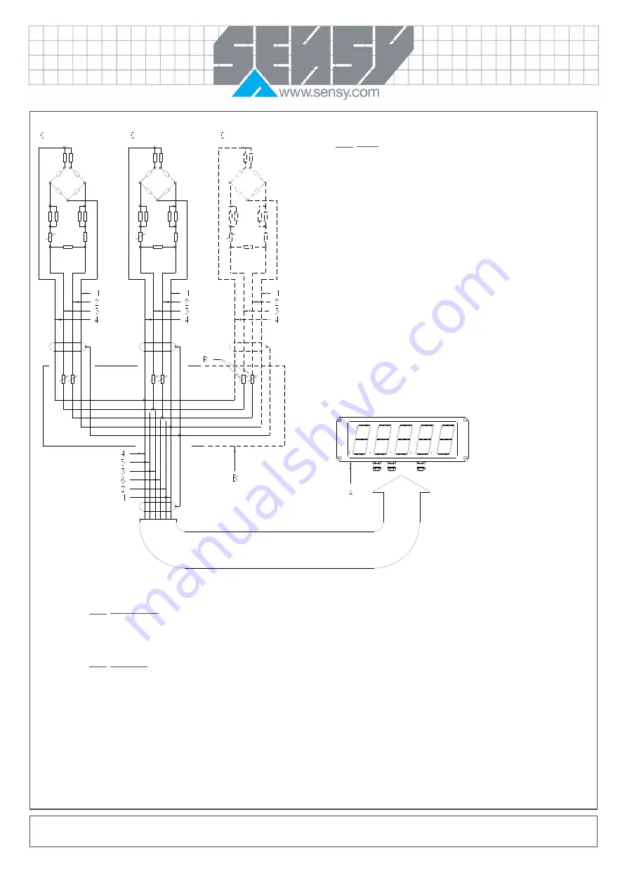
The cells must be installed in parallel, with the stranded mass wire joined to it. The sense must be joined to the cell supply, before the points of
parallel wiring and the stabilising resistances.
2.4.
Calibration
It must be done after the sensor has been turned on for a while (10-15 minutes) to obtain a uniform temperature of the installation. The cells do not
usually need to be adjusted with each other. However, when greater precision is needed, it is sometimes necessary to stabilise the cells individually
with the resistances in the junction box. Those resistances are of several ohms (±10) and are installed in the supply circuit. A parallel adjustable
resistance is mounted with a fixed resistance. The most sensitive cell will have its input resistance increased and the least sensitive will have its
lowest input resistance. You will see that it is preferable to work on both supply cables: schematic mounting is given for your information and allows
a variation of 0 to 20 ohms in series on the input impedance (2x10 ohms).
Note: A well known weight of more than 20% of the nominal load of the system can be expected. The calibration error is always much higher than
the error made on the evaluation of the load.
A) Display (ex. Dv680)
B) Junction box
C) Cell
R) Adjusting resistance
1) – out measure (green)
2) – in supply (yellow)
3) + in supply (brown)
4) + out measure (green)
5) Ref. (sense) + (pink)
6) Ref. (sense) + (grey)


