background image

Chapter 3: Installing the RTM II

11

RTM II FlexNet User Guide

DUG-10009-01

3.2.2 Logging In

Use your computer's Device Manager utility to identify which COM port the Sensus device is using, and 
then connect to the device and log in.

Identify the correct COM port

1.

Use the appropriate procedure for your Windows® operating system to open Device Manager.

2.

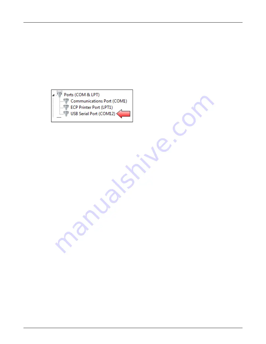
Expand Ports, and wait for Device Manager to show the COM port number for the Sensus device. 
This is the COM port you will select when you log in to Automation Device Configurator. For 
example:

Log in to Automation Device Configurator

1.

Open the Automation Device Configurator software.

2.

Select the COM port you identified in the previous steps and choose 

Connect

.

3.

Wait until you see “Ready” in the login window. If you see an error message in this window, verify 
that you have selected the correct COM port. Once the device is connected, you can log in.

4.

Type the password provided to you and choose 

Login

The Device Dashboard page shows the current status of the connected device including 
configuration settings, power information, and signal strength. The system automatically refreshes all 

Summary of Contents for RTM II FlexNet

Page 1: ...RTM II FlexNet Revision 1 DUG 10009 01 ...

Page 2: ...ights This Document and any copies or derivatives thereof must be returned immedi ately on demand This Document is subject to any applicable non disclosure agreement s Information in this Document is subject to change without notice and does not represent a commitment on the part of Sensus Copyright 2013 Sensus All Rights Reserved Sensus and the Sensus logo are registered trademarks of Sensus Flex...

Page 3: ...and can radiate radio frequency energy and if not installed and used in accordance with the instructions may cause harmful interference to radio communications However there is no guarantee that interfer ence will not occur in a particular installation If this equipment does cause harmful interference to radio or television reception which can be determined by turning the equipment off and on the ...

Page 4: ...any components inside the enclosure ATTENTION This device complies with Industry Canada license exempt RSS standard s Oper ation is subject to the following two conditions 1 this device may not cause inter ference and 2 this device must accept any interference including interference that may cause undesired operation of the device Le présent appareil est conforme aux CNR d Industrie Canada applica...

Page 5: ...ted power e i r p is not more than that necessary for successful communication Conformément à la réglementation d Industrie Canada le présent émetteur radio peut fonctionner avec une antenne d un type et d un gain maximal ou inférieur approuvé pour l émetteur par Industrie Canada Dans le but de réduire les risques de brouillage radioélectrique à l intention des autres utilisateurs il faut choisir ...

Page 6: ...vi Compliance Statements Document Number Document Name ...

Page 7: ...15 4 1 Getting Started with AutomationControl 15 4 2 Device History 19 4 3 Other AutomationControl Features 20 APPENDIX A BASIC INTEGRATION GUIDELINES 21 A 1 What You Need 21 A 2 Mount the RTM II 21 A 3 Connect RTM II to Antenna 23 A 4 Connect RTM II to IED 23 A 4 1 RS 232 Communications 23 A 4 2 Half Duplex 2 wire RS 485 Communications 24 A 4 3 Full Duplex 4 wire RS 485 Communications 24 A 5 Conn...

Page 8: ... 10009 01 RTM II FlexNet User Guide APPENDIX C HARDWARE SPECIFICATIONS 31 C 1 Processor 31 C 2 Communications 31 C 2 1 Ports 31 C 2 2 FlexNet Network 31 C 3 Enclosure 32 C 4 Operating Power 32 C 5 Environmental Data 32 ...

Page 9: ... and easy profile management through the AutomationControl software The RTM II communicates using the Sensus FlexNet private networks The multi address RTM II communicates with any IED that supports DNP3 or Modbus protocols Models with FlexNet radios communicate using packet data over the Sensus FlexNet private networks The devices can be installed on any FlexNet system using the latest Automation...

Page 10: ... generation Remote Terminal Units RTUs and IEDs use the standard DNP3 communication protocol to communicate with utility SCADA systems The RTM II also provides a Modbus interface to the many IEDs and RTUs that support this protocol The RTM II connects to an IED such as a recloser voltage regulator or capacitor bank controller through an RS 232 serial port or an optional RS 485 serial port The RTM ...

Page 11: ...eing received from the IED 3 FlexNet Radio Coverage Solid Green Successful power on power on call was received the Signal to Noise Ratio SNR is greater than 15 Blinking Green SNR is between 7 and 14 Off SNR is less than 6 or there is no communication from AutomationControl 4 RTM Status Blinking Green The RTM II is functioning normally On or Off There is a serious internal problem with the RTM II T...

Page 12: ...ccepts DNP unsolicited report by exception as well as constantly polling the IED to get the latest data When it discovers a reportable event for example a binary input that has changed state it initiates a report over the radio network to AutomationControl Here the data is validated and processed for distribution to the end user In addition control and configuration information can be sent from th...

Page 13: ...VDC The RTM II FlexNet Integration Guide gives complete instructions for installing the RTM II Note If your application does not come with an integration guide see Basic Integration Guidelines on page 21 for basic integration instructions 3 Verify communications remotely using AutomationControl or locally using the Sensus Automation Device Configurator utility This manual provides the information ...

Page 14: ...6 Chapter 1 Introduction DUG 10009 01 RTM II FlexNet User Guide ...

Page 15: ...Control Commissioning an RTM II involves the following tasks in the order listed Import the device into the system Create IED definitions Establish report intervals Create profiles Define sessions assign profile to session Update Configuration Settings Update Firmware For detailed explanations and step by step instructions refer to Commissioning Devices in the AutomationControl User Guide or Help ...

Page 16: ...8 Chapter 2 Commissioning Devices on AutomationControl DUG 10009 01 RTM II FlexNet User Guide ...

Page 17: ...n guide see Basic Integration Guidelines on page 21 for basic integration instructions 3 1 Before You Begin The Automation Device Configurator software comes with your integration kit Install the software on your PC You will need to connect the device to the PC that has the Automation Device Configurator software installed You can use a standard USB 2 0 cable with connector type A to connector typ...

Page 18: ...een installed and commissioned you can check the radio strength remotely using AutomationControl 3 2 1 Testing Locally with Automation Device Configurator Make sure the PC has the Automation Device Configurator software installed Connect the device to the PC 1 Using a standard USB 2 0 cable with Type A to Type B connectors shown in Figure 3 1 insert the cable into the PC Port on the bottom of the ...

Page 19: ... will select when you log in to Automation Device Configurator For example Log in to Automation Device Configurator 1 Open the Automation Device Configurator software 2 Select the COM port you identified in the previous steps and choose Connect 3 Wait until you see Ready in the login window If you see an error message in this window verify that you have selected the correct COM port Once the devic...

Page 20: ...verify that radio settings are correct See Troubleshooting Radio Communications on page 13 2 Configuration Loaded from AutomationControl A profile likely has not been configured for the device at the headend so a system administrator needs to do this before you can continue 3 IED N Online Status There is no communication to the IED Verify that the IED is connected powered on in online mode and tha...

Page 21: ...io Communications with AutomationControl The Sensus device is not communicating with AutomationControl through the base station Verify these communication settings are correct Send Radio Settings Restart If this button is red it means no radio parameters are loaded Contact your system administrator for the correct settings You may need to check with Sensus Automation Technical Support that your Au...

Page 22: ...14 Chapter 3 Installing the RTM II DUG 10009 01 RTM II FlexNet User Guide ...

Page 23: ... and to remotely control the equipment connected to the RTM II The following sections provide a brief overview of some of AutomationControl s basic functions For detailed descriptions and step by step instructions for using the software refer to the Automation Control User Guide or application Help 4 1 Getting Started with AutomationControl To log in to your account you need the user name and pass...

Page 24: ...list of active devices by Device ID and description The associated IED Any off normal conditions Device and IED status The existing signal strength A timestamp for the most recent communication from the device If a profile has not yet been transferred or assigned to a unit session it is shown as IED Name Pending ...

Page 25: ...ce product type RTM II RTM II TC032 T866 NaviComm current status of the device the current status of the associated IED signal strength and encryption status Signal Strength Indicator Colors and Values Green Excellent Greater than 11 Yellow Moderate 7 11 Red Weak 6 or below Point Data Based on the device profile this list shows the last reported binary input analog input and analog output values a...

Page 26: ...tomatic key rotation used with encryption FlexNet radio ID Route Information A base station routing summary for the device is shown here This list includes all base stations the device has communicated with Rank is based on the score The score is factored from the number of successful outbound commands to that base station the number of failed outbound commands to that base station and the last te...

Page 27: ...tory shows The origin of each report from the device or from AutomationControl Timestamps for the time the report was sent or received by AutomationControl and sent by the device DNP function description within the report refer to the standard DNP documentation for more details Unsolicited Anything AutomationControl did not request from the device Solicited Any request or command from AutomationCo...

Page 28: ...try for each point value reported Point Data History shows Point type index label and value Scaled point value definitions Units of measure Any off normal conditions Flags Timestamps for when the point data was reported Occurred At and when it was updated Device Time 4 3 Other AutomationControl Features For more information on the following AutomationControl features see the AutomationControl User...

Page 29: ...priate cable antenna combination Male female straight through serial cable or a null modem cable adapter 10 29 VDC power supply and or battery backup A 2 Mount the RTM II Some integrations come with a mounting plate If you have an integration that you would like to have a plate developed for please contact Sensus Automation Technical Support Otherwise the RTM II can be mounted to any available spa...

Page 30: ... Guide 2 Once your holes are drilled use 4 bolt nut pairs to secure the RTM II to the IED enclosure We recommend 4 40 x 3 8 inch pan bolt and Size 4 kepnuts Below are drawings of the RTM II dimensions connector locations and a drill hole diagram RTM II Mounting Hole Footprint ...

Page 31: ...SMA type cable connector Contact your sales representative for some possible cable antenna combinations or to place an order A 4 Connect RTM II to IED For help with a specific IED please contact Sensus Automation Technical Support A 4 1 RS 232 Communications To connect an RTM II to an IED with a RS 232 serial port you will need a serial cable to connect between the RTM II and the IED Each IED is d...

Page 32: ... 485 use the wiring diagram below RTM II IED1 IED2 TX RX RX TX RX RX RX TX TX RX TX TX Gnd Gnd Gnd A 5 Connect 10 29 VDC Power to RTM II The RTM II needs 10 29 VDC typically 170mA at 12 VDC with a maximum of 0 6A If you need data reported and the option to issue commands during a power outage the RTM II power supply will need battery backup If you only have 120 VAC available consider using an RTM ...

Page 33: ...D matches the point mapping inside the RTM II profile Port Setup Some IEDs need specific ports to be enabled for a certain protocol Ensure that the port you are using is enabled for the correct settings Parameter Rule Serial Information Baud Rate Data Bits Parity Stop Bits Must match IED Setup The default is 9600 8 N 1 Available Baud Rates are 100 150 300 600 1200 2400 4800 9600 19200 38400 115200...

Page 34: ...ons RS 232 Ports IED and PassThru 9 Pin Connector Terminal Block Pin Description Pin Description 1 Not Used 1 Tx 2 Tx 2 Rx 3 Rx 3 Ground 4 Tied to 6 5 Ground 6 Tied to 4 7 Tied to 8 8 Tied to 7 9 Not Used RS 485 Optional Port Configuration and Setup Terminal Block Pin Description 1 Rx 2 Rx 3 Tx 4 Tx 5 Term 6 Gnd ...

Page 35: ...sistor This is generally not needed Half Duplex Install a 120 Ohm resistor between the and signals Full Duplex On the master install a 120 Ohm resistor between the Rx and Rx signals On the farthest slave device install a 120 Ohm resistor between the Rx and Rx signals Data Line Polarity For communication to work the polarity of the two RS 485 lines must be correct Always connect signals to signals ...

Page 36: ...28 Appendix A Basic Integration Guidelines DUG 10009 01 RTM II FlexNet User Guide ...

Page 37: ...he parameters of the IED These can be changed using AutomationControl IED Configuration Many IEDs have different protocols available for their ports Whatever port you are using for the communication must be configured for the DNP protocol B 2 Radio Communication Issues Verify the device s ability to transmit and receive The device must be connected to power and an antenna attached in order to carr...

Page 38: ...ing data or responding to commands as expected you may not have the correct point rule mapping Verify that the IED is programmed with the correct parameters and that the RTM II is loaded with a matching profile If this is a new RTM II profile contact your profile administrator or Sensus Automation Technical Support for assistance ...

Page 39: ...rogram You can use a standard USB 2 0 cable with connector type A to connector type B like Belkin part F3U154 available at most computer or office supply stores as shown in the example below RS 232 SCADA communications port DB 9 female and terminal block Supports DNP 3 0 or Modbus depending on firmware RS 232 Pass Through for IED maintenance port connection DB 9 female C 2 2 FlexNet Network Two wa...

Page 40: ...onstruction Dimensions 5 6 H x 4 W x 1 7 D Optional NEMA 3R enclosure with 120 VAC 12 VDC power supply 11 H x 8 3 W x 3 3 D 3 lbs C 4 Operating Power 10 29 VDC typically 170mA at 12 VDC with a maximum of 0 6A 0 5 sec C 5 Environmental Data Operating temperature Range 40º to 70ºC Humidity 0 to 95 noncondensing Surge Suppression EN61000 4 4 and EN61000 4 5 Radiated emissions FCC Part 15 Class B EN 5...

Page 41: ...Appendix C Hardware Specifications 33 RTM II FlexNet User Guide DUG 10009 01 ...

Page 42: ...34 Appendix C Hardware Specifications DUG 10009 01 RTM II FlexNet User Guide ...

Reviews: