Network wiring (Silver/StarNeT 1000)
2 - 26 • • • MPS-4100 product guide
4. Set the Receiver modulation frequency to match the Transmitter modulation
frequency via JP1 and JP2.
5. Connect the Slave Receiver outputs for audio, alarm, self-test and tamper to
TB3. The return wire for the audio, alarm, self-test and tamper outputs may
be connected to any Common terminal on TB3. Connect the audio pair
shield to any Common terminal on TB3.
6. Configure the operating parameters via S1 and S2. See Table 2-4.
Slave Receiver
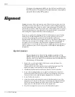
The Slave Receiver is wired according to the Relay Output method. Relay outputs
for alarm and tamper must be set for NC, 3 k
Ω
supervision via jumpers JP3, JP4,
JP5, and JP6. See Figure 2-10. The 3 k
Ω
EOL resistor for the tamper circuit must be
set at the Slave Transmitter.
If the Transmitter tamper is not being connected to the
Receiver, a jumper must be placed across pins 3 & 4 on TB2.
Figure 2-22 MPS-4100 Slave Receiver connections
Audio O/P
to Host Receiver
self-test I/P (12 VDC)
sensor alarm O/P to Host Receiver
tamper O/P
from Transmitter
tape shield
12 to 24 VDC O/P
to Transmitter
12 to 24 VDC I/P
from power supply
or from Host Receiver
tamper alarm O/P to Host Receiver
S2
1 2 3 4 5 6
JP4
JP6
JP5
JP3
JP1
JP2
S3
TAMPER SW
ALARM
JAM
WRONG
CHANNEL
CH6
CH5
CH4
CH3
CH2
CH1
LOCAL
AUDIO
sensitivity
JP7
3K
no 3K
NC
NO
NC NO
FAST SLOW
TAMPER
ALARM
TAMPER
RV3
ON
OFF
RV2
3K
no 3K
alarm
duration
RV1
MPS-4100
Microwave Receiver
COM
ALM 2
TMPR
TEST 2
COM
AUD 2
TB3
AUD PWR
DATA/
TEST TMP ALM
TB1
+
+
+
XMTTR
CONNECT
TMPR
PWR
TB2
+
P1
S1
1 2 3 4 5 6
ON
OFF


